


-
As an inertial instrument, the IFOG is an all-solid-state instrument that utilizes the Sagnac effect, and it has several advantages such as good stability, low power consumption, high reliability, etc. IFOG becomes one of the mainstream instruments in inertial navigation and strategic applications[1], which is widely used in aviation, aerospace, weapons systems and many industrial areas[2-4]. With the long-haul navigation and guidance requirements of the strategic-grade weapon launching platforms, submarines, large-scale surface ships and submarines, the requirements of precision are getting higher and higher[5-10], such as some applications require that the precision of the IFOG should be better than 0.001 (°)/h in the geomagnetic field of 0.5 Gs.
Magnetic non-reciprocity is one of the main non-reciprocal error sources of IFOGs[11-12]. Methods for suppressing magnetic non-reciprocity include software compensation, fiber coil compensation and magnetic shielding, etc. The software compensation method uses a magnetometer to measure the strength of a magnetic field and then make use of the test results, compensating the magnetic field error by software method[13]. This method only focuses on the axial magnetic field[14]. In the fiber coil compensation method, multiple compensating fiber coils are installed in the IFOG as well as a sensitive fiber coil, which will make the size and weight of the IFOG increase, and make the sensitive angular velocity of the IFOG become more complicated. Magnetic shielding method is widely used in engineering[15-17]. However, in order to meet the requirements of high-precision IFOGs, it is necessary to use two or more layers of materials for shielding effectiveness, which will obviously increase the weight and volume of IFOG.
In this paper, we analyse the effect of magnetic non-reciprocity on the bias error of IFOG and propose methods of improvement that make the fiber de-twist to reduce the magnetic field sensitivity of the fiber coil and connect the shielding materials by laser welding to increase the shielding effectiveness. Through these improvements, the precision of the fiber coil in the magnetic field and temperature environment is improved.
-
Magnetic non-reciprocity includes Faraday non-reciprocity and non-Faraday non-reciprocity. Faraday non-reciprocity is a magneto-optical phenomenon, when the polarization-maintaining fiber coil which has a birefringence of Δβ is located in a magnetic field that parallels to the radial direction of the fiber coil. The two linearly polarized lights that transmit in opposite directions in fiber coil will induce a phase shift
$\Delta \mathop \phi \nolimits $ :$$ \Delta \mathop \phi \nolimits_{} = \dfrac{{2\pi \Delta \beta L}}{\lambda } = 2VHL $$ (1) where V is the Verdet constant, H is the magnetic field strength.
Ideally, the two lights that propagate in opposite directions can form a closed loop, and the circular birefringence phase difference can offset each other. But when the fiber is twisted, as shown in Fig.1, it will cause additional circular birefringence and induce a phase shift as[18]:

Figure 1. Schematic diagram of twisting of fiber
$$ \Delta {\varphi _R} = \dfrac{{4VH}}{{\Delta \beta }}{\displaystyle\int\limits_0^L }{\tau ({\textit{z}})} {\rm{sin}}\left(\dfrac{{\textit{z}}}{r} - {\theta _0}\right){\rm{d}}{\textit{z}}$$ (2) where L is the length of the fiber coil, r is the radius of the fiber coil, τ(z) is the twist rate of the fiber, and θ0 is the angle of the magnetic field and the plane of the fiber coil.
Non-Faraday non-reciprocity effect is that when the fiber is wound into a fiber coil, the fiber will be bent, so that the refractive index of the fiber near the axis of the fiber coil is always greater than the refractive index of the fiber far from the axis, which will cause a mode drift of the transmitted light in the axial magnetic field and produce a phase shift[11] as:
$$ \Delta \mathop \phi \nolimits_A {\rm{ = }}12\dfrac{{VH\lambda }}{n}N $$ (3) where N is the turn number of the fiber coil.
According to Eq.(2) and Eq.(3), the bias drift of the IFOG induced by magnetic non-reciprocity can be expressed as:
$$ \Delta {\varOmega _R} = \dfrac{{4VH}}{{\Delta \beta K}}\displaystyle\int\limits_0^L {\tau ({\textit{z}})} {\rm{sin}}\left(\dfrac{{\textit{z}}}{r} - {\theta _0}\right){\rm{d}}{\textit{z}} $$ (4) $$ \Delta \mathop \varOmega \nolimits_A {\rm{ = }}12\dfrac{{VH\lambda }}{{nK}}N $$ (5) where K is the scale factor of the IFOG.
It can be known from Eq.(4) and Eq.(5) that the bias drift of the IFOG is proportional to the strength of the magnetic field, either in the axial magnetic field or in the radial magnetic field. In addition, the bias error is also related to the twist rate of fiber. Therefore, in order to reduce the influence of magnetic field on the bias error of IFOG, we need to reduce the strength of magnetic field and the twist rate of fiber.
In practical application environment, in order to reduce the influence of the magnetic field, the fiber coil is usually shielded by permalloy material of high permeability[16], The shielding method is to place the fiber coil in the cavity that is formed by the base and the upper cover, and then connect the base and the upper cover by screws. As the base and the upper cover are made of permalloy, which will realize the shielding of fiber coil from the magnetic field[19]. Using this method, the magnetic field strength can be attenuated by 23 dB with 2 mm thickness permalloy material, which achieves a good magnetic shielding effectiveness and meets the using of low- and medium-precision IFOGs. However, for high-precision IFOGs, that attenuation does not meet the application requirements. As the fiber coil has a typical magnetic field sensitivity of 1 (°)·h−1·Gs−1[12], when the IFOG precision is better than 0.001 (°)/h in the geomagnetic field of 0.5 Gs, the attenuation of magnetic field strength is required to be higher than 54 dB. Thus, the above shielding method is no longer used; Besides, the 2 mm thick material will lead to an increase in the weight of the IFOG.
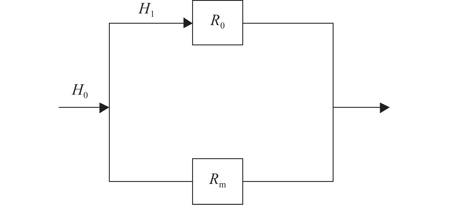
When the permalloy material is used to shield the geomagnetic field, the shielding diagram is shown in Fig.2, and the equivalent circuit diagram is given in Fig.3. Theoretically, since the magnetic resistance of the permeability material is much smaller than the air magnetic resistance, it has a good shielding effectiveness, but there is a gap when the base and the outer cover are connected by screws, which can cause an increase in magnetic resistance of the connection and result in poor shielding effectiveness. From Fig.2 and Fig.3 , the H1 can be obtained as:

Figure 2. Shielding diagram of the geomagnetic field

Figure 3. Shielding equivalent circuit diagram of the geomagnetic field
$$ {H_1} = \dfrac{{{R_{\rm{m}}}}}{{{R_{\rm{m}}} + {R_0}}}{H_0} $$ (6) And the shielding effectiveness SE is:
$$ \begin{split} S\!\!E = &20{\rm{lg}}\left( {\dfrac{{{H_0}}}{{{H_1}}}} \right)=20{\rm{lg}}\left( {\dfrac{{{R_{\rm{m}}} + {R_0}}}{{{R_{\rm{m}}}}}} \right){\rm{ = }}\\ & 20{\rm{lg}}\left( {1 + \dfrac{{{R_0}}}{{{R_{\rm{m}}}}}} \right) \end{split} $$ (7) where Rm is the magnetic resistance of the material, R0 is the magnetic resistance of the air, H1 is the strength of the magnetic field inside the shielding cavity, H0 is the strength of the magnetic field outside the shielding cavity.
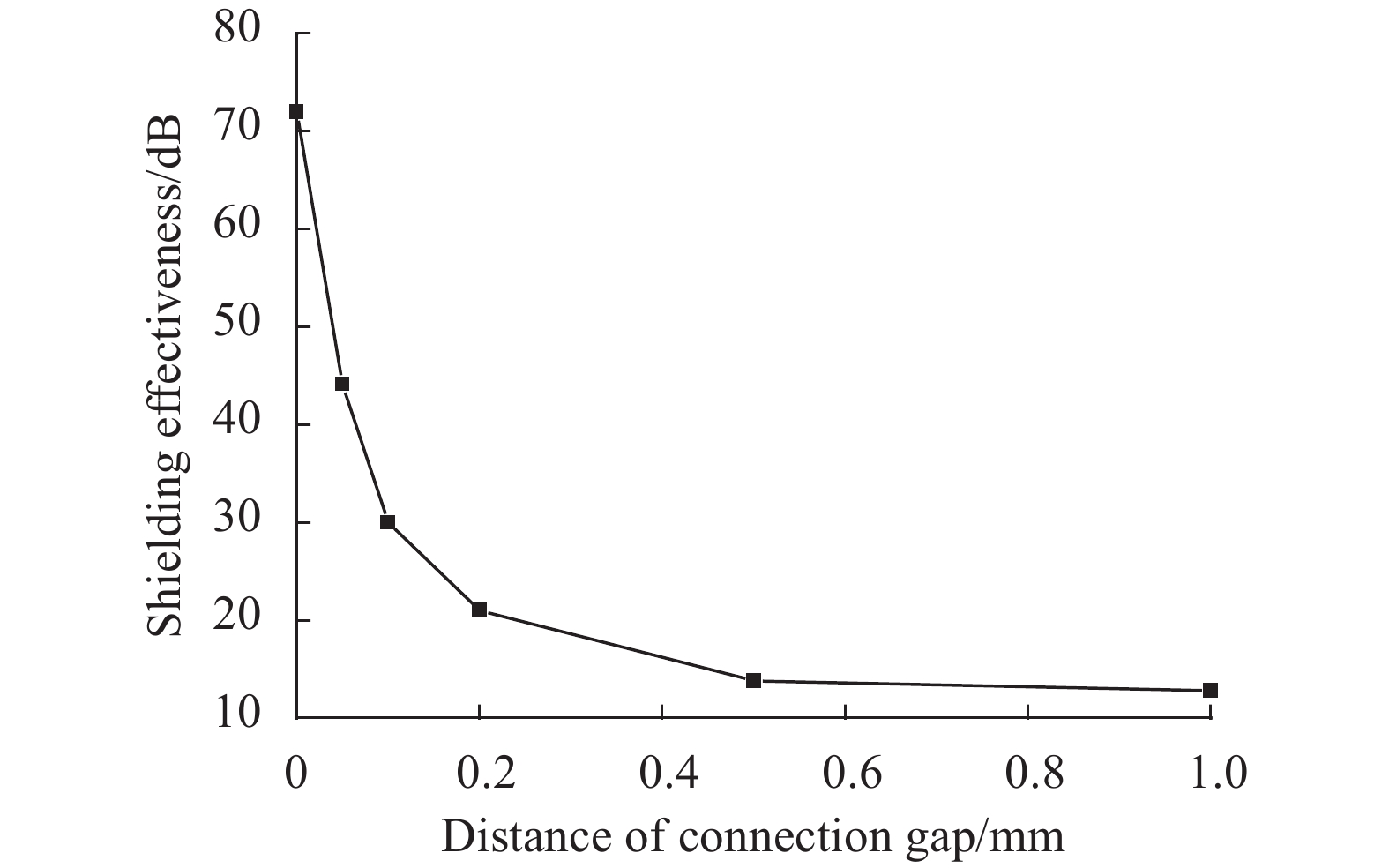
It can be seen from Eq.(6) and Eq.(7) that when there is a gap in the connection of the shielding material, the magnetic resistance will increase and the shielding effectiveness will reduce. Figure 4 is the simulation relationship between the distance of the axial connection gap of the shielding material and the attenuation of the strength of the internal magnetic field. It can be seen that the shielding efficiency will decrease sharply when there is connection gap between the shielding materials.

Figure 4. Relationship between the distance of the axial connection gap and the attenuation of the strength of internal magnetic field
In order to improve the shielding effectiveness, it is necessary to reduce the influence of the gap. In this paper, we connected the base and the cover by laser welding, which can avoid the connection gap. In addition, when the connection gap was welded by laser, it can also reduce the influence of air convection and improve the precision of the fiber coil[20].
From Eq.(4) we know the magnetic field sensitivity of the fiber coil S is:
$$ S {\rm{ = }}{\varOmega _R}/H = \dfrac{{4V}}{{\Delta \beta K}}\displaystyle\int\limits_0^L {\tau ( {\textit{z}})} {\rm{sin}}\left(\dfrac{ {\textit{z}}}{r} - {\theta _0}\right){\rm{d}}z $$ (8) $$ {\rm{set}}\;\tau ({\textit{}}{\textit{z}}) = {\tau _0}{\rm{sin}}\left(\dfrac{{\textit{z}}}{r}\right) $$ (9) $$ {\rm{We }}\;{\rm{can }}\;{\rm{obtain}}\;\;\;{{S }} = \dfrac{{2V{\rm{cos}}{\theta _0}}}{{\Delta \beta K}}L{\tau _0} $$ (10) So S is proportional to the t0. When V=90 μrad·Gs−1·m−1, λ=1550 nm, r=50 mm, Δβ=2 000 rad/m, θ0=0, and τ0=100 (°)/m, we can find S=13.3 (°)·h−1·Gs−1, which cannot meet the application requirements. In fact the twist rate of fiber is not constant, but randomly distributed along the fiber. It can be from 0 (°)/m to thousands (°)/m, so it is difficult to compensate. In this paper, we make the fiber de-twist before the fiber coils were wound. The method is to measure the torque in the fiber through some sensors, and feed back the test results to the control end. The control end makes the rotating motor start work, the angle of fiber twist is offset by the angle of motor rotation, and the fiber is de-twisted.
-
In order to test the effect of fiber de-twist on the field sensitivity of the fiber coil, we fabricated three fiber coils whose fiber was with de-twist and three fiber coils whose fiber was without de-twist, and test the axial magnetic field sensitivity of the fiber coil in the magnetic field of±5 Gs, ±10 Gs, ±20 Gs, ±30 Gs, ±40 Gs.
In order to test the effect of the connection gap that was welded by laser on the shielding effectiveness of the fiber coil, we made the fiber coil whose fiber has been de-twisted into three different states, as Fig.5 shows: (1) The fiber coil is not shielded, marked as state 1 (as shown in Fig.5(a)); (2) The fiber coil is shielded by the base and the upper cover that was made of permalloy material; the connection gap of the base and the upper cover was connected by screws, marked as the state 2 (as shown in Fig.5(b)) ; (3) The fiber coil is shielded by the base and the upper cover, the connection gap was welded by laser, marked as state 3 (as shown in Fig.5(c)). We put the fiber coil in the Faraday magnetic field generator system, set the magnetic field strength as ±5 Gs, ±10 Gs, ±20 Gs, ±30 Gs, ±40 Gs respectively, and the bias of the IFOG was tested.

Figure 5. Diagrammatic cross-section of the fiber coils in three different states
In order to test the influence of the connection gap that was welded by laser on the temperature performance of the fiber coil, the fiber coils in state 2 and state 3 were placed in the temperature chamber. The temperature of the test is from −40 ℃ to 60 ℃, the rate of temperature change is 1 ℃/min and the hold time of the highest and lowest temperature is 60 min, and the bias of the IFOG was tested.
-
The magnetic field sensitivity of the fiber coil is shown in Tab.1. It can be seen that the magnetic field sensitivity of the fiber coil whose fiber has been de-twisted is about 10.6% of that fiber without de-twist, so the fiber de-twist can effectively reduce the magnetic field sensitivity of the fiber coil.
Table 1. Magnetic field sensitivity of the fiber coil
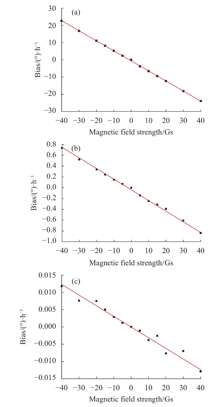
No. Magnetic field sensitivity of the fiber coil /(°)·h−1·Gs−1 - Fiber without de-twist Fiber with de-twist 1 16.235 2 1.810 6 2 11.383 9 1.052 3 3 13.802 5 1.528 4 Average 13.807 2 1.463 8 The bias of the IFOG in different magnetic field strength is shown as Fig.6. We find that there is a linear relationship between the bias of IFOG and the magnetic field strength: the greater the magnetic field strength is, the greater the influence on the bias is, which is consistent with the theoretical analysis. When the shielding state is different, the magnetic field sensitivity of the fiber coil will differ greatly, as shown in Fig.6 and Tab.2. Compared to the fiber coil in state 1, the fiber coil in state 2 has a good shielding effectiveness, which can achieve to 34.8 dB, but as there is a gap in the connection, the magnetic field sensitivity of the fiber coil in state 2 can only reduce to 0.026 5 (°)·h−1·Gs−1, which cannot meet the requirements of high-precision IFOG. However, when the connection gap was welded by laser, as the fiber coil in state 3, the shielding effectiveness can be improved to 64 dB, and the magnetic field sensitivity of the fiber coil can be reduced to less than 0.000 4 (°)·h−1·Gs−1, which greatly improves the precision of the fiber coil in the magnetic field.

Table 2. Magnetic field sensitivities of the coil in different states
Axial Magnetic field sensitivity
of state 1 /(°)·h−1·Gs−1Magnetic field sensitivity
of state 2 /(°)·h−1·Gs−1Shielding effectiveness
of state 2Magnetic field sensitivity
of state 3 /(°)·h−1·Gs−1Shielding effectiveness
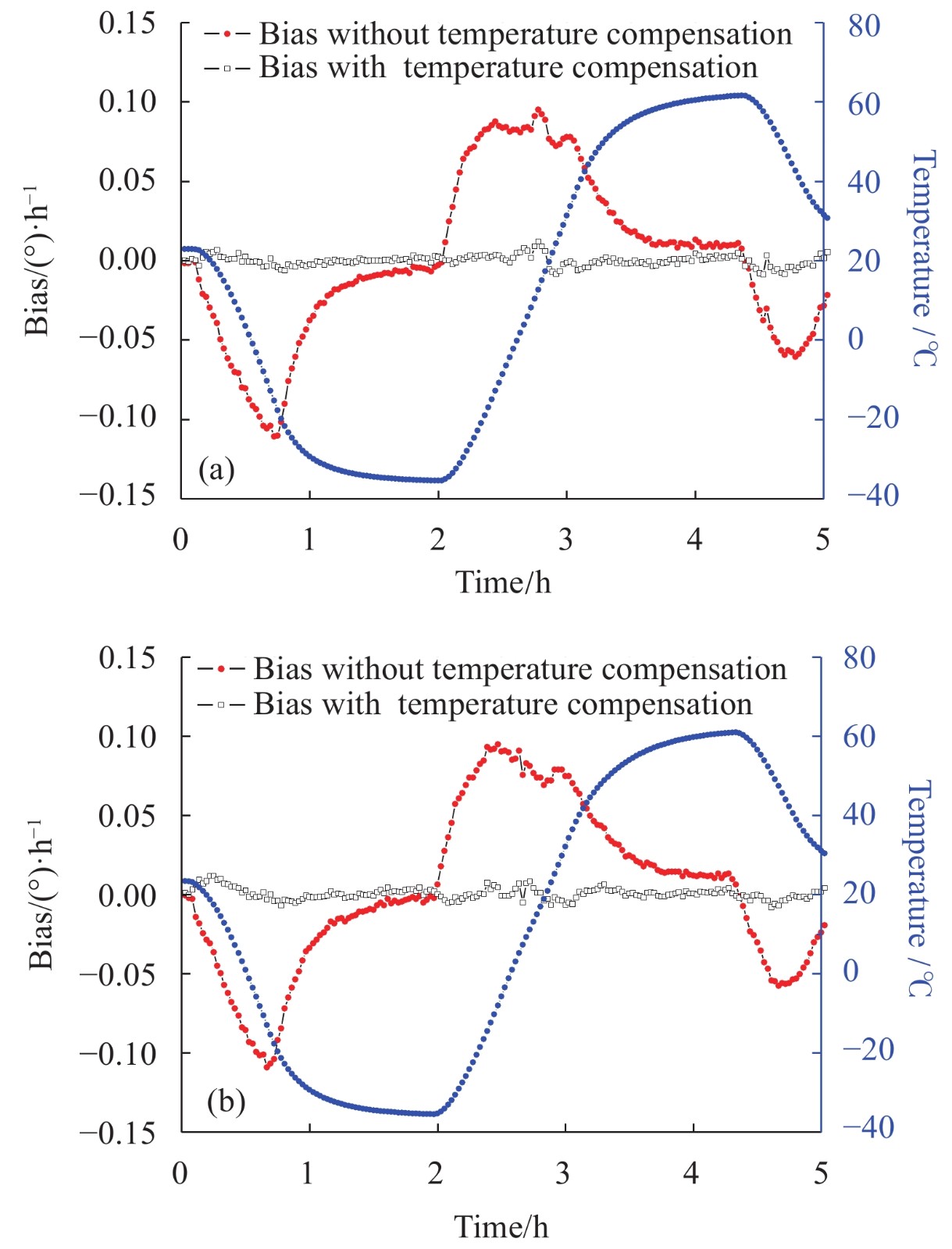
of state 3X 1.052 3 0.026 5 31.98 0.000 40 68.40 Y 0.584 4 0.018 1 34.83 0.000 31 64.70 Z 0.395 4 0.008 0 33.88 0.000 23 64.71 Notes: The fiber coil in state 1 was un-shielding; The fiber coil in state 2 was shielded by permalloy material, but the connection gap was not welded; The fiber coil in state 3 is shielded by permalloy material, and the connection gap was welded by laser. The bias of the IFOG in different temperatures is shown in Fig.7 and Tab.3. We can find that when the connection gap was welded by laser, the precision of the IFOG in different temperature can be improved by more than 7.5%.

Table 3. Bias stability of the IFOG in the temperature of −40−60 ℃
States Uncompensated bias stability Compensated bias stability Connection gap unwelded 0.041 0 (°)/h 0.003 18 (°)/h Connection gap welded 0.036 5 (°)/h 0.002 94 (°)/h Performance improvements 11.0% 7.5% -
In this paper, we analyse the effect of magnetic non-reciprocity magnetic fields on the bias error of IFOG. According to the analysis results, we propose methods of improvement that make the fiber de-twist to reduce the magnetic field sensitivity of the fiber coil and connect the shielding materials by laser welding to increase the shielding effectiveness. Through the measurement of fiber de-twist, the magnetic field sensitivity of the fiber coil is reduced by 89.3%; Through the improvement of laser welding, the shielding effectiveness of the permalloy material is improved from 31 dB to at least 64 dB, the magnetic field sensitivity of the fiber coil is reduced from 0.026 5 (°)·h−1·Gs−1 to less than 0.000 4 (°)·h−1·Gs−1, the bias stability of the IFOG in different temperature is improved by more than 7.5%. These test results show that these improvements can improve the precision of IFOG in the magnetic field and temperature environment, and meet the performance requirements of high-precision IFOG.
-
摘要: 光纤环在磁场中产生磁致非互异性误差,成为制约高精度干涉型光纤陀螺(以下简称高精度光纤陀螺)应用的主要因素之一,而误差与磁场强度、光纤扭转率有关。由于光纤扭转导致的光纤环磁场灵敏度达到10 (°)·h−1·Gs−1以上,即使采用坡莫合金对磁场屏蔽,屏蔽效能仅能达到30 dB左右,难以满足高精度光纤陀螺的应用需求。文中通过等效电路模型和有限元仿真分析了屏蔽材料连接缝隙对屏蔽效能的影响,通过公式计算了扭转率对磁场灵敏度的影响。根据分析,提出了将屏蔽材料由螺钉连接改为激光焊接并对光纤进行退扭的改进方法。通过光纤退扭,光纤环磁场灵敏度降低了89.3%;通过对连接缝隙激光焊接,屏蔽效能由 31 dB 提高到 64 dB以上,磁场灵敏度由 0.026 5 (°)·h−1·Gs−1 降低到了 0.000 4 (°)·h−1·Gs−1以下,且变温环境下陀螺零偏稳定性提高了7.5%以上。改进措施能够提高光纤环在磁场和温度环境下的精度,满足高精度光纤陀螺性能要求。
-
关键词:
- high-precision IFOG /
- magnetic field /
- connection gap /
- laser welding /
- de-twist
Abstract: The magnetic non-reciprocity error of fiber coil is one of the main factors that restrict the application of high-precision IFOG, and the error is related to the strength of magnetic field and the twist rate of fiber. The magnetic field sensitivity of fiber coil is more than 10 (°)·h−1·Gs−1 due to the twisting of the fiber, even if permalloy is used to shield the magnetic field, the shielding effectiveness can only reach about 30 dB, which cannot meet the requirements of high-precision IFOG. The influence of the connection gap between shielding materials on shielding effectiveness was analysed by an equivalent circuit model and finite element simulation, the influence of the twist rate on the magnetic field sensitivity was deduced by formula. Through these analyses, the improvements were proposed that changed the connection of shielding materials from screw connection to laser welding and made the fiber de-twist. Through the measurement of fiber de-twist, the magnetic field sensitivity of the fiber coil was reduced by 89.3%; Through the improvement of laser welding, the shielding effectiveness was improved from 31 dB to at least 64 dB, the magnetic field sensitivity was reduced from 0.026 5 (°)·h−1·Gs−1 to less than 0.000 4 (°)·h−1·Gs−1, and the bias stability of the IFOG in different temperature was improved by more than 7.5%. These improvements can improve the precision of the fiber coil in the magnetic field and temperature environment, meeting the performance requirement of high-precision IFOG.-
Key words:
- high-precision IFOG /
- magnetic field /
- connection gap /
- laser welding /
- de-twist
-
Figure 4. Relationship between the distance of the axial connection gap and the attenuation of the strength of internal magnetic field
Table 1. Magnetic field sensitivity of the fiber coil
No. Magnetic field sensitivity of the fiber coil /(°)·h−1·Gs−1 - Fiber without de-twist Fiber with de-twist 1 16.235 2 1.810 6 2 11.383 9 1.052 3 3 13.802 5 1.528 4 Average 13.807 2 1.463 8  下载: 导出CSV
Table 2. Magnetic field sensitivities of the coil in different states
Axial Magnetic field sensitivity
of state 1 /(°)·h−1·Gs−1Magnetic field sensitivity
of state 2 /(°)·h−1·Gs−1Shielding effectiveness
of state 2Magnetic field sensitivity
of state 3 /(°)·h−1·Gs−1Shielding effectiveness
of state 3X 1.052 3 0.026 5 31.98 0.000 40 68.40 Y 0.584 4 0.018 1 34.83 0.000 31 64.70 Z 0.395 4 0.008 0 33.88 0.000 23 64.71 Notes: The fiber coil in state 1 was un-shielding; The fiber coil in state 2 was shielded by permalloy material, but the connection gap was not welded; The fiber coil in state 3 is shielded by permalloy material, and the connection gap was welded by laser.
下载: 导出CSV
Table 3. Bias stability of the IFOG in the temperature of −40−60 ℃
States Uncompensated bias stability Compensated bias stability Connection gap unwelded 0.041 0 (°)/h 0.003 18 (°)/h Connection gap welded 0.036 5 (°)/h 0.002 94 (°)/h Performance improvements 11.0% 7.5%
下载: 导出CSV
-
[1] Wang Wei. Development of new inertial technology and its application in aerospace field [J]. Infrared and Laser Engineering, 2016, 45(3): 0301001. (in Chinese) [2] Lefèvre H C. The fiber-optic gyroscope, a century after Sagnac’s experiment: The ultimate rotation-sensing technology? [J]. Comptes Rendus Physique, 2014, 15(10): 851-858. doi: 10.1016/j.crhy.2014.10.007 [3] Xue Lianli, Chen Shaochun, Chen Xiaozhen. Development and review of foreign inertial technology in 2017 [J]. Navigation and Control , 2018, 17(2): 1-9. (in Chinese) [4] Qian Weizhu, Yang Libao. A fiber optic gyro error compensation method based on wavelet neural network [J]. Chinese Optics, 2018, 11(6): 1024-1031. (in Chinese) doi: 10.3788/co.20181106.1024 [5] Udd E, Pickrell G, Du H H, et al. Fiber optic gyro development at honeywell [C]//Fiber Optic Sensors and Applications XIII, 2016: 985201-985214. [6] Deppe O, Dorner G, Konig S, et al. MEMS and FOG technologies for tactical and navigation grade inertial sensors-recent improvements and comparison [J]. Sensors, 2017, 17(3): 1-22. [7] Udd E, Pickrell G, Du H H, et al. Potpourri of comments about the fiber optic gyro for its 40th anniversary, and how fascinating it was and it still is! [C]//Fiber Optic Sensors and Applications XIII, 2016: 985201-985210. [8] Wu Junwei, Miao Lingjuan, Li Fusheng, et al. Compensation method of FOG temperature drift with improved support vector machine [J]. Infrared and Laser Engineering , 2018, 47(5)-0522003. (in Chinese) [9] Li Hongcai, Liu Chuntong, Zhao Xiaofeng, et al. Modeling and analysis of fiber optic gyroscope dynamic northfinding algorithm based on Simulink [J]. Infrared and Laser Engineering , 2018, 47(S1): 122001. (in Chinese) [10] Liu Junhao, Li Ruichen. Analysis of thermal drift in high performance interferometric fiber-optic gyroscopes [J]. Chinese Optics, 2020, 13(2): 333-343. (in Chinese) doi: 10.3788/co.20201302.0333 [11] Logozinskii V N. Magnetically induced non-Faraday nonreciprocity in a fiber-optic gyroscope [J]. Journal of Communications Technology and Electronics, 2006, 51(7): 836-840. doi: 10.1134/S1064226906070175 [12] Toldi E D, Guattari F, Molucon C, et al. Understanding and control of the magnetic sensitivity of a fiber-optic gyroscope [C]//2016 DGON Intertial Sensors and Systems (ISS), 2016: 1-15. [13] Cai Haoyuan, Li Wenkuan, Zhao Shenglin, et al. Gyro-compensated real-timeEKF magnetic field calibration method [J]. Optics and Precision Engineering , 2019, 27(12): 2650-2658. (in Chinese) doi: 10.3788/OPE.20192712.2650 [14] Zhou Y, Zhao Y, Tian H, et al. Theory and compensation method of axial magnetic error induced by axial magnetic field in a polarization-maintaining fiber optic gyro [J]. Optical Engineering , 2016, 55(12): 126101-126107. [15] Mark J G, Tazartes D A, Amado C, et al. High efficiency magnetic shield for a fiber optic gyroscope: US, US5896199[P]. 1999-04-20. [16] Chen Yaozhou, Wang Xiaxiao, Gao Yangyang, et al. Research on the influence mechanism of earth’s magnetic field on zero bias of high precision FOG [J]. Electronic Measurement Technology, 2016, 39(1): 147-150. (in Chinese) [17] Tian Hui, Liang Cui, Zhang Dengwei. Magnetic shielding technique for high-precision FOGs [J]. Transducer and Microsystem Technologies, 2019, 38(7): 61-63. (in Chinese) [18] Hotate K, Tabe K. Drift of an optical fiber gyroscope caused by the faraday effect: influence of the earth’s magnetic field [J]. Applied Optics , 1986, 25(7): 1086-1092. doi: 10.1364/AO.25.001086 [19] Li Jintao, Fang Jiancheng. Magnetic shielding method and experiment study of inertial measurement unit based on high precision fiber-optic gyro-scope [J]. Acta Aeronautica et Astronautica Sinica, 2011, 32(11): 2106-2116. (in Chinese) [20] Lv Xiaoqin, Huang Xinyan, Gao Feng, et al. Influence of air pressure variation on FOG bias stability and its improvement [J]. Journal of Chinese Inertial Technology , 2015, 23(3): 399-401, 408. (in Chinese) -

 点击查看大图

图(7) / 表(3)
计量
- 文章访问数: 821
- HTML全文浏览量: 260
- PDF下载量: 66
- 被引次数: 0


