


-
自20世纪80年代,16兆DRAM的产生,标志着世界开始进入超大规模集成电路(VLSI)阶段,VSLI成为所有高科技领域发展的基础[1]。集成电路的集成度按照摩尔定律(Moore's Law)增长,每隔18~24个月电路上承载的元件数量就会增加一倍,到2014年,英特尔宣布了行业首个14 nm处理器,摩尔定律还将继续驱动集成电路的发展。先进的超大规模集成电路的制造是一个庞大的系统工程,它包括五个制造阶段:(1)硅片制备:包括晶体生长、滚圆、切片及抛光等工序;(2)硅片制造:包括硅片清洗、成膜、光刻、刻蚀和掺杂等工序;(3)硅片测试:通过测试识别有缺陷的芯片,使其被淘汰而不进入下一道工艺流程;(4)装配与封装:包括将硅片切割成芯片、压焊和包封,器件封装一般采用金属封装、陶瓷封装、陶瓷金属封闭和塑料封装;(5)终测:对每一个完成封装的集成电路进行测试,确保芯片的功能和质量。全部研制过程涉及约800道工序,且某些工序在制备过程中重复使用多次[2-5]。其中,硅片制造阶段是将一整套集成电路永久刻蚀在裸露的硅片上的过程。而光刻被认为是大规模集成电路制造中的核心步骤,把每个晶体管元件越做越小的关键是先进的光刻技术,新一代集成电路的出现总是代表当时最先进的光刻技术水平[6-9]。从这个意义上讲,光刻技术是集成电路制造工艺发展的驱动力,相比其他单个制造工艺而言,光刻对芯片性能的发展有着革命性的贡献。在工业生产中应用最广泛的是分辨率为100~500 nm的芯片,该分辨率光源波长为365 nm。文中针对近紫外光刻照明系统中变焦系统进行了设计,并对其误差源进行详细分析最终确定公差范围,在掩模面上可实现高均匀照明,对改善最终的曝光质量具有重要的意义[10-12]。
-
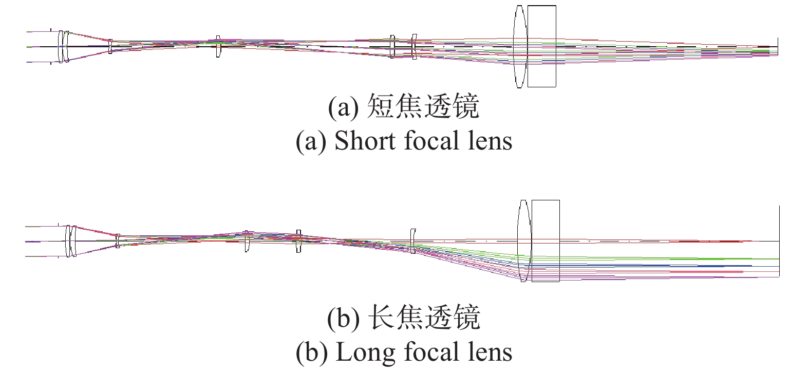
变焦系统的设计要求中心波长365 nm,入瞳直径Φ33 mm,视场角±1.35°,像面直径Φ30~120 mm,后工作距离≥200 mm,像方远心度≤10 mrad,畸变≤±2%。根据变焦系统的设计要求,采用CODE V软件设计的变焦系统光路如图1所示,设计结果和满意度分析如表1所示。

图 1 变焦系统的光路图
Figure 1. Optical path diagram of the zoom system
表 1 设计结果与设计要求对照表
Table 1. Comparison table of design results and design requirements
Parameters Design requirements Design results Wavelength/nm 365 365 Entrance pupil diameter/mm 33 33 Field/(°) ±1.35 ±1.35 Image surface diameter/mm Φ30-120 Φ30-120 After working distance/mm ≥200 300 Image surface
telecentric degrees/mrad≤10 ≤5.1 Distortion ≤±2% ≤±0.6% -
在分析变焦系统的误差源对系统的影响时主要考虑对光瞳性能的影响,包括相干因子大小、远心度(质心变化)、椭圆度和极平衡性。不同误差源对光瞳性能的影响是不同的,具体分析如下。
-
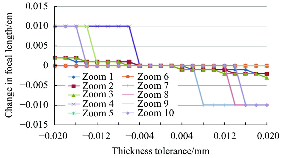
变焦镜组的单面厚度误差主要影响各个zoom的焦距,对各zoom的远心度、视轴移动没有影响,图2、3分析了变焦镜组第2面~第15面(第1面为光阑面)的厚度误差对各zoom焦距的影响。

图 2 第2面厚度误差对焦距的影响
Figure 2. Influence of the thickness error of the second surface on the focal length

图 3 第15面厚度误差对焦距的影响
Figure 3. Influence of the thickness error of the 15th surface on the focal length
从以上分析可以看到,前组的各面厚度误差对焦距的影响大于后组各面的厚度误差,其中第2片的厚度(第4面)和第2、3片透镜间厚度(第5面)的误差对焦距的影响最大。厚度误差20 μm时最大的焦距变化量为4 mm。由于焦距的变化量需控制在5.4 mm内,因此厚度公差需控制在20 μm以内。
-
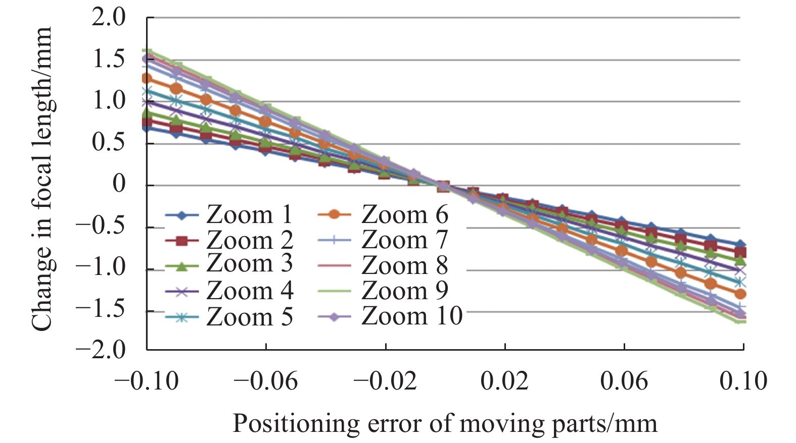
变焦镜组内有3片动件,其移动定位的误差会造成各个zoom的焦距误差,因此,需分析动件的移动定位误差对焦距的影响,如图4所示。

图 4 动件1移动精度对焦距的影响
Figure 4. Influence of the moving accuracy of moving part 1 on the focal length
通过以上对动件移动精度的分析可知,变焦系统的3个运动件移动精度要求基本相同。动件的移动精度为0.5 mm时,焦距变化大约为2 mm。从以上动件精度分析、面间隔变化分析等可知,动件的移动精度控制在0.5 mm以内即可满足要求。
-
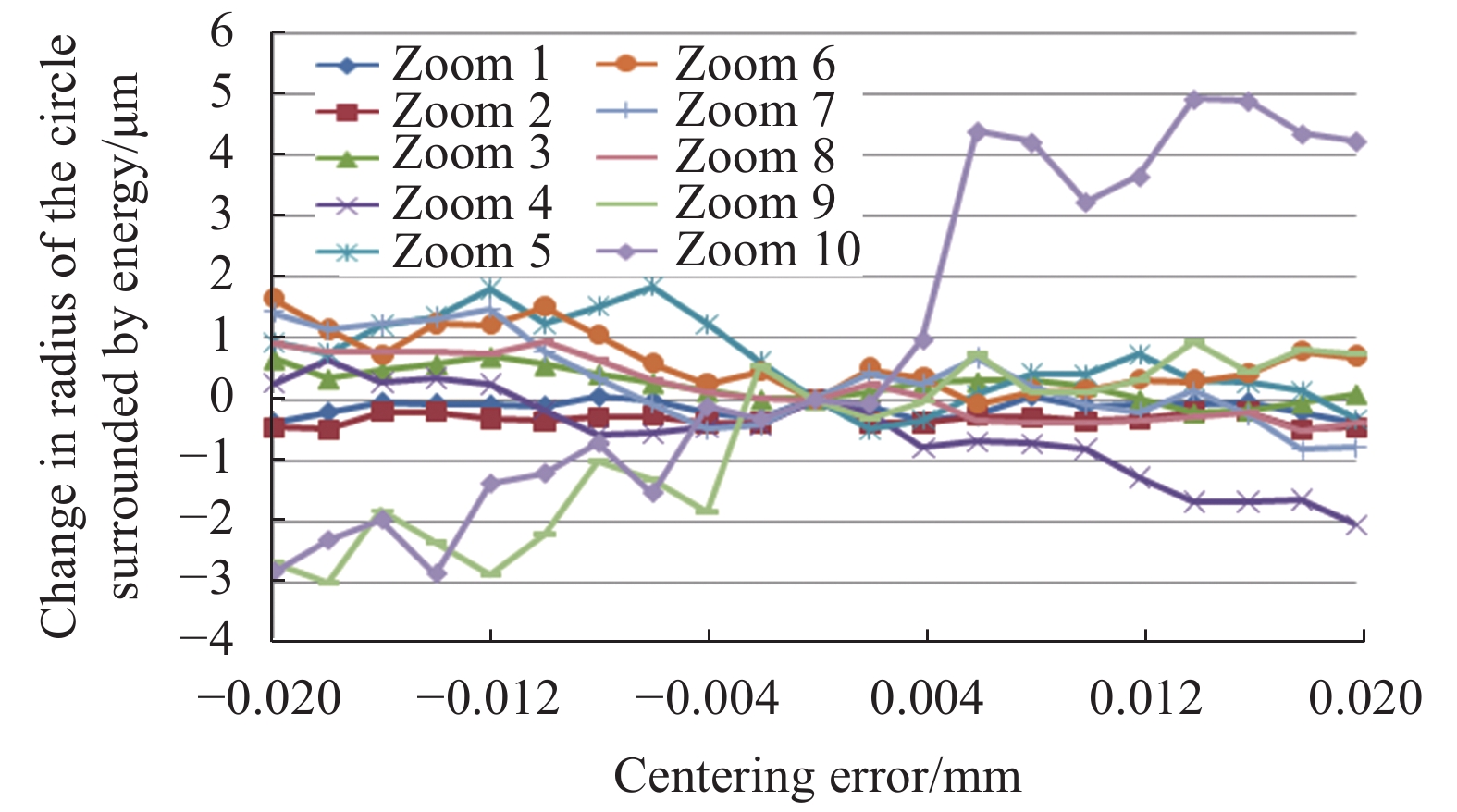
各透镜的偏心差主要影响变焦镜组的视轴移动、远心度和90%能量包围圆半径。因此分析了个透镜偏心差对这些参数的影响,如图5~7所示。

图 5 透镜1偏心误差对视轴移动的影响
Figure 5. Influence of eccentricity error of lens 1 on the visual axis movement

图 6 透镜1偏心误差对远心度的影响
Figure 6. Influence of eccentricity error of lens 1 on telecentric degree

图 7 透镜1偏心误差对90%能量包围圆半径的影响
Figure 7. Influence of eccentricity error of of lens 1 on the radius of 90% energy encircling circle
通过分析发现,透镜的偏心误差对远心度和能量包围圆半径的影响较小,对视轴移动的影响较明显,偏心0.02 mm最大的视轴移动量为0.4 mm左右,但仍然在可接收的范围内,因此,透镜的偏心误差控制在0.02 mm之内即可。
-
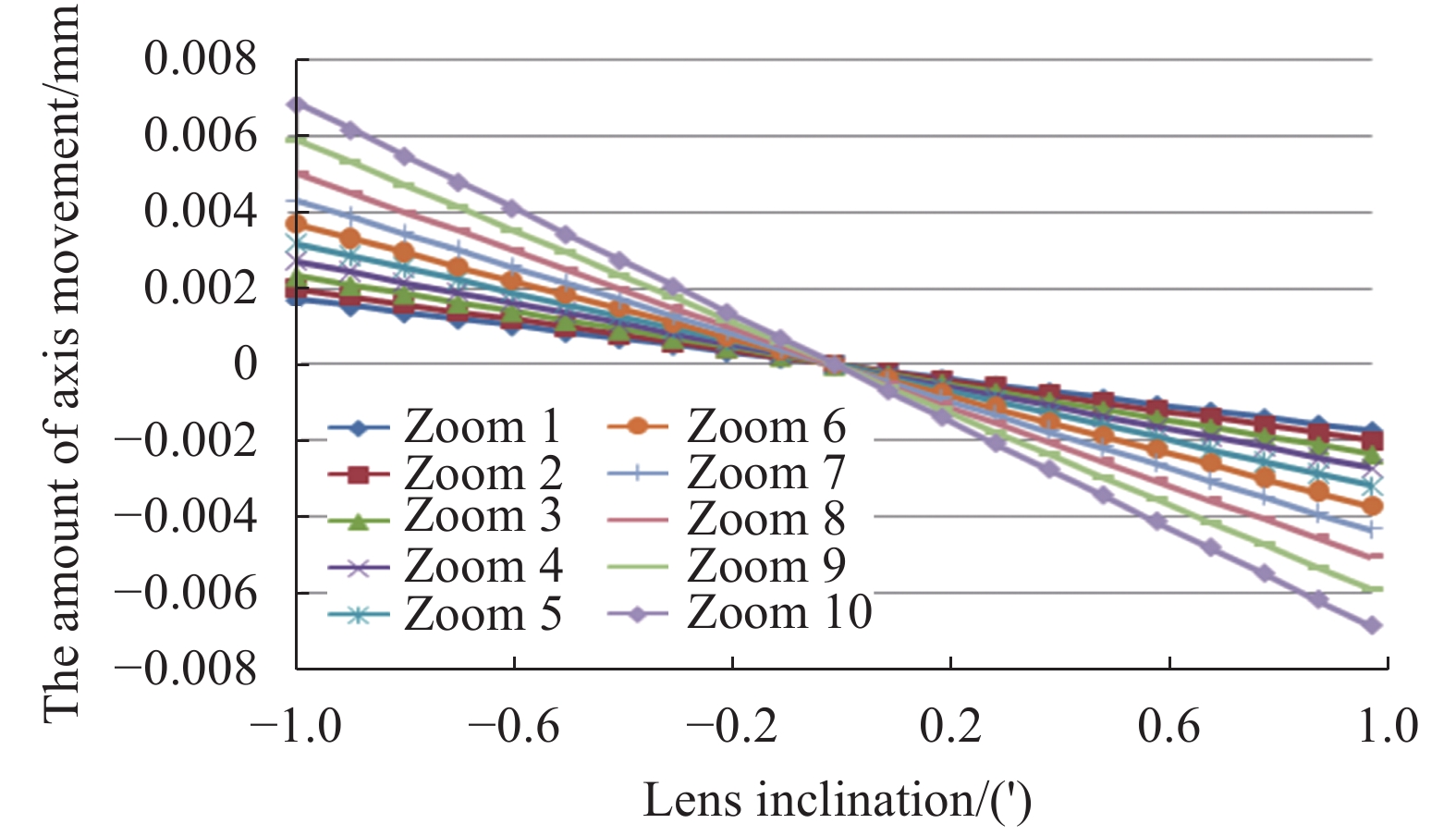
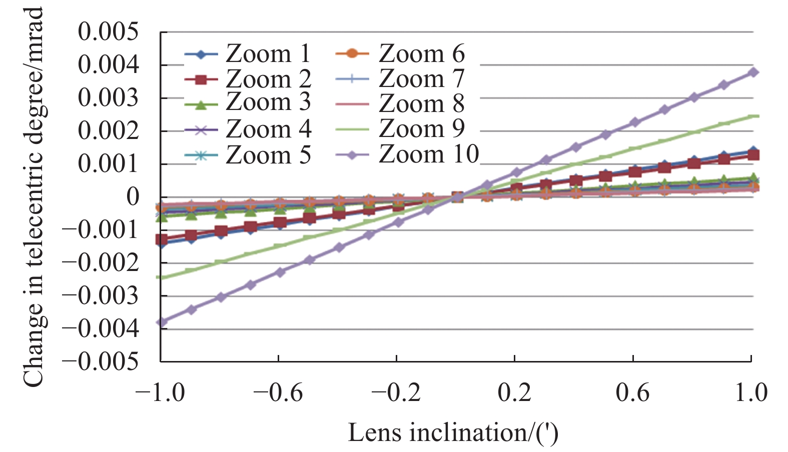
各透镜的倾斜误差主要影响变焦镜组的视轴移动、远心度和90%能量包围圆半径,因此分析了各透镜的倾斜误差对这些参数的影响,如图8~10所示。

图 8 透镜1倾斜误差对视轴移动的影响
Figure 8. Influence of the tilt error of lens 1 on the visual axis movement

图 9 透镜1倾斜误差对远心度的影响
Figure 9. Influence of tilt error of lens 1 on telecentric degree

图 10 透镜1倾斜误差对90%能量包围圆半径的影响
Figure 10. Influence of the tilt error of lens 1 on the radius of the 90% energy encircling circle
通过分析发现,透镜的倾斜误差对视轴移动、远心度和能量包围圆半径的影响都很小,公差很松,倾斜1′以上各个参数的变化量都还很小,因此,各透镜的倾斜误差控制在1′之内即可。
-
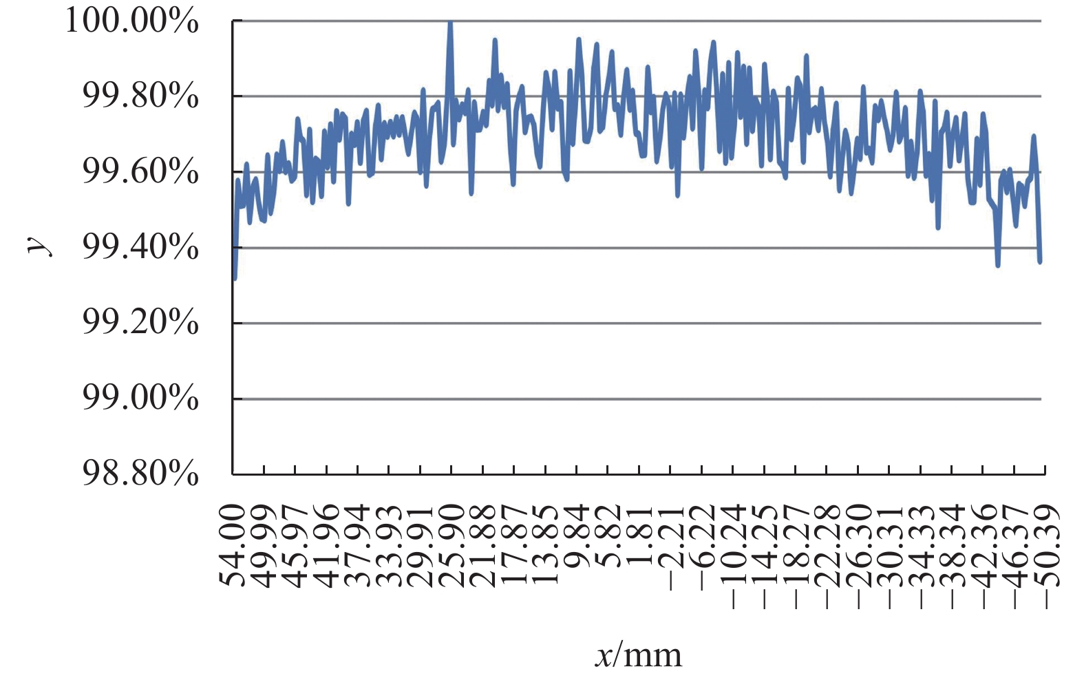
对于相干因子约为0.16的传统照明,追迹10亿条光线,计算获得掩模面能量分布y向积分沿x方向的光能分布曲线,如图11所示,从仿真计算可得掩模面光强不均匀性值为1.95%,满足指标要求。

图 11 y向积分沿x方向的光能分布曲线
Figure 11. y-direction integral light energy distribution curve along the x-direction
-
采用CODE V软件完成了紫外光刻照明系统中变焦系统的设计,设计结果为波长365 nm,入瞳直径33 mm,视场±1.35°,相面直径Φ30~120 mm,后工作距离300 mm,像方远心度≤5.1 mrad,畸变≤±0.6%,各指标均满足技术要求。主要分析了变焦系统中单面厚度、动件移动精度、各透镜偏心和各透镜倾斜的误差源对系统光瞳性能的影响,结合变焦系统的设计方案和实际加工能力,给出合理的公差范围。测试结果验证了制定公差合理、可行。
Design and tolerance analysis of the zoom system in 365 nmUV lithography illumination system
-
摘要: 照明系统是投影光刻曝光光学系统的重要组成部分,它实现的功能是为掩模面提供高均匀性照明、控制曝光剂量以及不同照明模式。变焦系统作为光刻照明系统的重要组成部分,对提高整个光刻机的性能起着至关重要的作用。文中针对紫外光刻照明系统的特点,采用CODE V软件完成了波长365 nm,入瞳直径Φ33 mm,像方远心度≤10 mrad,畸变≤±2%近紫外光刻照明系统中变焦系统的设计,分析了变焦系统的误差源对系统光瞳性能的影响,结合变焦系统的设计方案和实际加工能力,给出单面厚度公差需小于20 μm,动件移动精度小于0.5 nm,各透镜偏心公差小于0.02 mm,各透镜倾斜公差控制在1′之内。制定公差合理、可行,满足了紫外光刻照明系统高均匀性、高能量利用率的要求。Abstract: The illumination system is an important part of the projection lithography exposure optical system. Its function is to provide high uniformity illumination and control the exposure dose and different illumination modes for the mask surface. As an important part of the lithography lighting system, the zoom system plays a vital role in improving the performance of the entire lithography machine. According to the characteristics of the ultraviolet lithography illumination system, this paper uses CODE V software to complete the design of the zoom system in the near ultraviolet lithography illumination system with a wavelength of 365 nm, an entrance pupil diameter of Φ33 mm, an image telecentricity ≤10 mrad, and a distortion ≤±2%. The effect of the error source of the zoom system on the pupil performance of the system is analyzed, combined with the design scheme of the zoom system and the actual processing capability, gives a single-sided thickness tolerance of less than 20 μm, a moving part movement accuracy of less than 0.5 nm, and an eccentric tolerance of less than 0.02 mm for each lens. The tilt tolerance of each lens is controlled within 1′. The tolerances are reasonable and feasible, and meet the requirements of high uniformity and high energy utilization of the UV lithography illumination system.
-
图 2 第2面厚度误差对焦距的影响
Figure 2. Influence of the thickness error of the second surface on the focal length
图 3 第15面厚度误差对焦距的影响
Figure 3. Influence of the thickness error of the 15th surface on the focal length
图 4 动件1移动精度对焦距的影响
Figure 4. Influence of the moving accuracy of moving part 1 on the focal length
图 5 透镜1偏心误差对视轴移动的影响
Figure 5. Influence of eccentricity error of lens 1 on the visual axis movement
图 6 透镜1偏心误差对远心度的影响
Figure 6. Influence of eccentricity error of lens 1 on telecentric degree
图 7 透镜1偏心误差对90%能量包围圆半径的影响
Figure 7. Influence of eccentricity error of of lens 1 on the radius of 90% energy encircling circle
图 8 透镜1倾斜误差对视轴移动的影响
Figure 8. Influence of the tilt error of lens 1 on the visual axis movement
图 10 透镜1倾斜误差对90%能量包围圆半径的影响
Figure 10. Influence of the tilt error of lens 1 on the radius of the 90% energy encircling circle
图 11 y向积分沿x方向的光能分布曲线
Figure 11. y-direction integral light energy distribution curve along the x-direction
表 1 设计结果与设计要求对照表
Table 1. Comparison table of design results and design requirements
Parameters Design requirements Design results Wavelength/nm 365 365 Entrance pupil diameter/mm 33 33 Field/(°) ±1.35 ±1.35 Image surface diameter/mm Φ30-120 Φ30-120 After working distance/mm ≥200 300 Image surface
telecentric degrees/mrad≤10 ≤5.1 Distortion ≤±2% ≤±0.6%  下载: 导出CSV
-
[1] 赵阳. 深紫外光刻复杂照明光学系统设计[D]. 中国科学院长春光学精密机械与物理研究所, 2010. Zhao Yang. Design of complex illumination optical system for deep ultraviolet lithogrpahy[D]. Changchun: Changchun Institute of Optics, Fine Mechanics and Physics, Chinese Academy of Sciences, 2010. (in Chinese) [2] Dorodnyy A, Shklover V, Braginsky L, et al. High-efficiency spectrum splitting for solar photovoltaic [J]. Solar Energy Materials & Solar Cells, 2015, 136(10): 120-126. [3] Zhang L, Liu D, Shi T, et al. Practical and accurate method for aspheric misalignment aberrations calibration in non-null interferometer testing [J]. Applied Optics, 2013, 52(35): 8501-8511. doi: 10.1364/AO.52.008501 [4] 张巍, 巩岩. 投影光刻离轴照明用衍射光学元件设计[J]. 光学精密工程, 2008, 16(11): 2081-2086. doi: 10.3321/j.issn:1004-924X.2008.11.007 Zhang Wei, Gong Yan. Design of diffractive optical elements for off-axis illumination in projection lithography [J]. Opt Precision Eng, 2008, 16(11): 2081-2086. (in Chinese) doi: 10.3321/j.issn:1004-924X.2008.11.007 [5] 宋强, 朱菁, 王健. 基于混合梯度下降的高性能光刻机离轴照明衍射光学元件设计[J]. 光学学报, 2015, 35(1): 0122005-1-0122005-9. Song Qiang, Zhu Jing, Wang Jian. A mixed gradient algorithm for high performance DOE design in off axis lithography illumination system [J]. Acta Optica Sinica, 2015, 35(1): 0122005. (in Chinese) [6] 张巍, 梁传样, 李金, 等. 用于激光数字投影显示系统的匀光整形元件设计[J]. 光学学报, 2015, 35(80): 0805001-1-0805001-8. Zhang Wei, Liang Chuanyang, Li Jin, et al. Design of opticelements for beam shaping and unigorm illumination in laser digital projection display system [J]. Acta Optica Sinica, 2015, 35(8): 0805001. (in Chinese) [7] 李美萱, 李宏, 张斯淇, 郭明, 付秀华. 基于浸没式光刻光束稳定系统的反射镜[J]. 光子学报, 2019, 48(02): 46-55. Li Meixuan, Li Hong, Zhang Siqi, et al. Research on mirrors of beam stabilization system for immersion lithography [J]. Acta Photonica Sinica, 2019, 48(2): 0222003. (in Chinese) [8] 李美萱, 王丽, 董连和. 光刻曝光系统中新型光可变衰减器的研制[J]. 中国激光, 2018, 45(01): 135-140. Li Meixuan, Wang Li, Dong Lianhe, et al. Development of a novel optical variable attenuator in lithography exposure system [J]. Chinese Journal of Lasers, 2018, 45(1): 0103002. (in Chinese) [9] 李美萱, 王丽, 董连和. 浸没式光刻照明系统中非球面变焦系统[J]. 光子学报, 2018, 47(1): 0120002. Li Meixuan, Wang Li, Dong Lianhe. Design of aspherical zoom optical system in immersion lithography lighting system [J]. Acta Photonica Sinica, 2018, 47(1): 0120002. (in Chinese) [10] 李美萱, 李宏, 张斯淇, 张文颖, 郭明. 基于离散抽样加密算法的衍射光学元件设计[J]. 红外与激光工程, 2019, 48(9): 0916004. Li Meixuan, Li Hong, Zhang Siqi, et al. Design of diffractive optical element based on discrete sampling encryption algorithm [J]. Infrared and Laser Engineering, 2019, 48(9): 0916004. (in Chinese) [11] Li Meixuan, Kan Xiaoting, Wang Meijiao. Design and analysis on a novel uniform compensator in lithography lighting system [J]. Laser & Infrared, 2019, 49(1): 105-109. (in Chinese) [12] Li Meixuan, Wang Meijiao, Wang Li, et al. Design and tolerance analysis of compound eye lens in lithography lighting system [J]. Laser & Infrared, 2017, 47(7): 842-847. (in Chinese) -

 点击查看大图
计量
- 文章访问数: 189
- HTML全文浏览量: 54
- PDF下载量: 67
- 被引次数: 0

