


-
随着技术的不断发展,高分辨率、轻小型空间光学载荷成为研究热点。空间载荷的运载和运行环境非常复杂,在发射过程中会受到冲击、振动等干扰,在轨运行过程中会受到压力、温度、重力等影响,这些因素都会造成光学载荷离焦现象,从而影响成像质量[1-2]。为了满足光学系统成像要求,需要对光学载荷在轨离焦进行修正。
根据载荷类型不同,调焦的方式也不尽相同,常用的调焦方式为机械式调焦,根据所调节的对象不同主要可分为镜组调焦[3]、反射镜移动调焦[4-5]、像面移动调焦[6-7]等方式。机械调焦一般采用步进电机作为驱动装置、编码器作为角位置传感器、精密滚珠丝杠作为传动机构,所组成的机构系统来实现位置的调节[8-9]。这类调焦机构在调焦精度较高的同时也具有较大范围的调焦行程[10]。但是,由于所承载的反射镜或焦面系统的质量一般较大且机构系统相对复杂,使调焦机构质量一般也较大、装配难度高且成本也高,不利于空间遥感相机的轻量化、批量化和低成本设计。
热控调焦方法是通过控制光机结构的热膨胀来进行焦面位置的调节,这种方式不需要额外的机构系统,仅通过相机热控和光机结构的设计来实现,从而降低了结构的复杂性和质量[10]。对于空间相机常用的光学系统构型如卡塞格林式,系统离焦量对于次镜位置的变化最为敏感,针对次镜的热控调焦技术已应用于Pleiades 和 SEOSAT 空间相机[11-13]。 Raval详细介绍了Pleiades HR相机次镜热控调焦的原理及结构设计[14]。Butler等人介绍了300 kg级遥感卫星SpaceEye-1搭载的EOS-D载荷所使用的两种热控调焦结构,并通过热弹性分析方法评估了热控调焦范围[15]。Alberto等人设计了一种应用于空间光学遥感相机的次镜双向热控调焦装置来实现±15 μm的次镜位置调节,并开展了相应的热学仿真和试验[16]。目前,国内外次镜热控调焦技术主要以次镜热控装置的设计来实现。
文中提出了一种基于载荷支撑结构温度控制实现载荷调焦的新型热控调焦方式,来进一步实现轻量化、紧凑设计,使在轨调焦技术更适用于光学载荷批量制造。首先,通过调焦精度分析,确定主承力支撑结构的设计要求;其次,基于拓扑优化技术进行支撑结构设计;然后,介绍热光学试验确定调焦系数的方法;最后,基于此设计的“吉林一号”高分03星光学载荷完成了地面及在轨试验验证。
-
光学载荷离焦误差与其焦深有关。当焦平面的法线位移量小于1/4半焦深时,光学系统成像仍然清晰,当焦平面的法线(或沿光轴方向)位移量大于1/4半焦深时,光学系统成像质量明显下降[17]。焦深由光学系统相对孔径决定,公式(1)为焦深计算公式。为保证光学系统成像质量,要求调焦精度小于1/4半焦深。
式中:δ为光学系统焦深;F为光学系统相对孔径的倒数;λ为入射光波波长。
卡塞格林式是使用最广泛的两镜系统,系统焦平面法线位移量与次镜直线位移量成正比,公式(2)为不同材料支撑结构热控调焦范围。
式中:L0为光学载荷支撑结构尺寸;CTE为光学载荷支撑材料线胀系数;ΔT为温度变化范围;β为光学系统焦平面法线位移量与次镜法线位移量比值。
目前应用于空间载荷支撑结构的材料主要包括钛合金、高体份铝基复合材料、铟钢、碳纤维复合材料。表1为采用不同材料的支撑结构在10 ℃控温范围内所对应的系统焦平面调焦范围。材料选取要综合考虑材料比刚度、线膨胀系数、加工工艺以及光学载荷热控调焦范围等。由于碳纤维和铟钢线膨胀系数过低不适合热控调焦;高体份铝基复合材料线膨胀系数与钛合金相近,但加工难度太大,成本也较高,所以综合考虑选取钛合金作为该支撑结构的材料。
Material Specific stiffness Thermal expansion coefficient Focusing range
/mmTC4 25.9 9.1/10−6 K−1 9.1×10⁻⁵βL0 SiCp/Al 61.2 8/10−6 K−1 8×10⁻⁵βL0 Invar 17.4 0.54/10−6 K−1 5.4×10⁻⁶βL0 M40 42.3 0 0 Table 1. Thermal refocusing range of different materials for support structure of space optical payloads
-
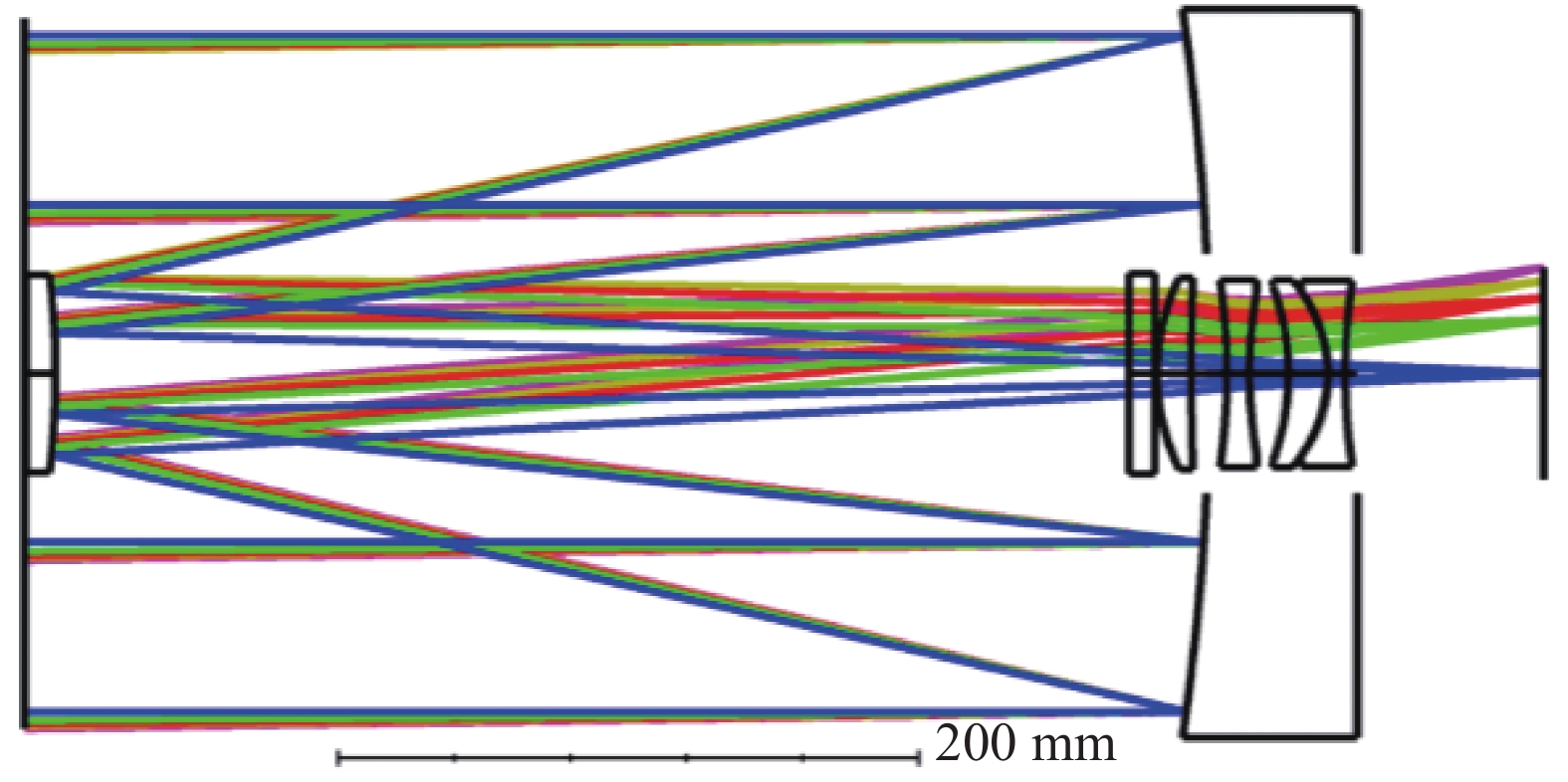
文中研究的光学载荷采用卡塞格林加校正镜系统形式,总体要求质量小于8 kg,分辨率优于1 m,相对孔径为1/9.42。载荷光学系统如图1所示。根据焦深公式(1)计算光学系统焦深为0.195 mm,即调焦精度应小于0.024 mm。光学系统焦平面法线位移量是次镜直线位移量的22.5倍,主、次镜间距为397.3 mm,根据公式(2)预估选用钛合金支撑结构材料10 ℃温度调焦范围为0.813 mm。

Figure 1. Zemax model of optical system
光学系统公差分析要求次镜相对于主镜偏心和倾斜公差分别为10 μm和10″,综合考虑光学元件加工、系统装配等因素,光学载荷在温度、重力等工况,主、次镜三个方向的位移偏差应小于5 μm,倾斜不大于5″。
-
通过连续拓扑优化变密度法来进行优化分析,变密度法(SIMP)是将有限元模型设计空间每个单元的“Density”作为设计变量[18]。该“单元密度”同结构的材料参数优化有关,0~1之间连续取值,优化求解后单元密度为1(或靠近1),表明此处材料很重要,需要保留;相反为0,则可以去除。
建立有限元模型,以质量点替代次镜组件,约束支撑结构底部12个安装点的6个自由度,建立支撑结构和集成优化数学模型如公式(3)所示:
式中:Vc为支撑结构的体积分数;dx和θx分别为次镜在重力工况下X方向的偏心与倾斜;f1为支撑结构的第一阶特征频率。
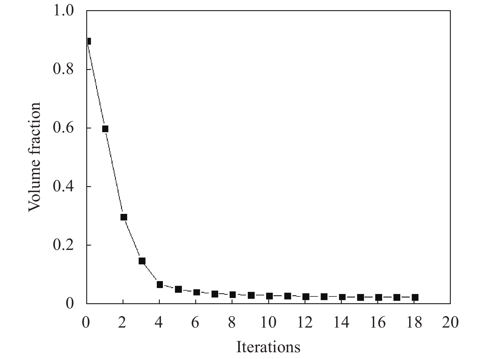
图2所示模型在经过18轮迭代优化后,优化结果趋于收敛,图3为最终的拓扑优化结果云图。支撑结构采用底环与支撑杆结合的形式,半筒半杆式结构有效提高大长细比桁架杆结构的结构刚度;工字型交错翻边结构提高底部刚度;次镜支撑L型翻边提高了支撑结构顶部刚度,对次镜组件抵抗重力偏心与倾斜具有重要作用;支撑杆采用大尺寸中空薄片结构,降低重量的同时,提高了支撑结构的稳定性。

Figure 2. Curve of volume fraction and iterations
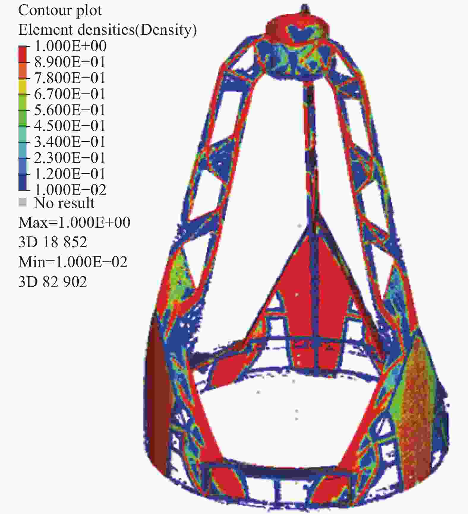
Figure 3. Result of topology optimization design
-
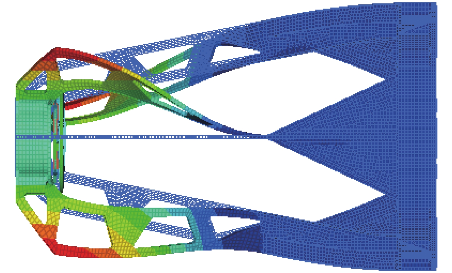
为保证光学系统成像质量,要求其支撑结构必须具有良好的动态刚度,以使载荷工作时在外界机械扰动下不产生抖动。光学载荷结构动态刚度主要取决于结构的动态特性,主要由结构的自然频率与振型来衡量,载荷结构的自然频率越大,表明结构的动态刚度越高。图4为光学载荷支撑结构一阶模态,经分析一阶固有频率为109 Hz。
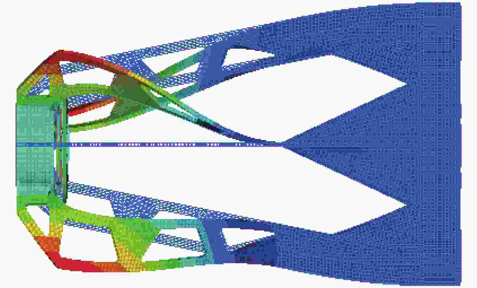
Figure 4. 1st modal shape of support structure
光学载荷装调环境、各反射镜的加工环境均为地面重力场,而其工作环境为空间微重力的环境。光学载荷发射后,在轨受力的方向和大小均发生改变,进而影响到其成像质量。定义X向为重力方向,对光学载荷进行静力学分析,分析结果如表2所示。分析结果表明:次镜相对主镜偏心为4.6 μm,倾斜3.9″,满足光学系统公差要求,该支撑结构具有足够的刚度来克服重力作用对空间相机在地面装调、检测、成像等过程中的影响。
Mirror Eccentric Tilt ΔX/μm ΔY/μm ΔZ/μm θX/(″) θY/(″) θZ/(″) Primary mirror Datum Datum Datum Datum Datum Datum Second mirror 4.6 0.02 - 0.02 3.9 - Table 2. Static analysis results
支撑结构三杆控温不均匀主、次镜偏心产生影响,从而影响光学载荷的成像质量,表3为温度不均性(0.4 ±0.2) ℃分析结果,由次镜偏心引起的光学系统传函下降了0.38%,对成像影响较小。
±0.2 ℃ Eccentric Tilt ΔX/μm ΔY/μm ΔZ/μm θX/(″) θY/(″) θZ/(″) Second mirror −0.001 5 1.838 1 0.519 −1.971 3 0.028 5 None Table 3. Analysis results of temperature inhomogeneity
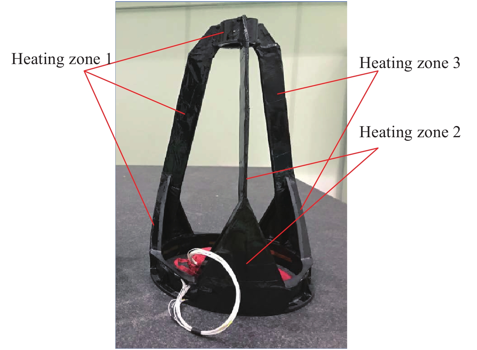
支撑结构共设置4个主动控温加热区,粘贴2层导热石墨片,将等效导热效率由8 W/m提升至80 W/m,提高支撑结构的等温性。3个支撑杆各布置一个测温点,为了保证支撑结构采温精度,需要对支撑结构采温热敏电阻进行标定。利用标准电阻对每一路测温电路进行标定后,可使采温电路的采温精度达到±0.03 ℃以内,从而满足温度控制指标。综合分析,光学载荷支撑结构温度不均匀性要求±0.2 ℃。
图5为热控实施后的支撑结构图。在保证支撑结构清洁状态下,首先按照加热带位置布置热敏电阻和加热片;其次进行热控系统布线、粘贴导热膜,并进行回路阻值检验;最后进行多层安装与绝缘检验。

Figure 5. Supporting structure with thermal system
-
对光学载荷进行有限元分析,计算支撑结构在温度均匀变化下,主、次镜空气间隔变化值和各光学元件曲率变化值,将分析结果输入光学系统计算其变化引起焦平面法线位移量,表4为分析结果。支撑结构温度变化与焦平面法线位移量呈线性关系,其方程为:
式中:t为控温温度差值;
$ \sigma $ 为焦平面直线位移量。“吉林一号”高分03星光学载荷热控调焦系数为0.077 3 mm/℃。通过合理热设计、热敏电阻精确标定,支撑结构热控控温精度为±0.2°,根据公式(4)计算调焦定位精度理论值为±0.015 mm,小于1/4半焦深。
Support structure temperature change/℃ 5 4 3 2 1 Focal position change/mm 0.382 0.311 0.234 0.157 0.079 Table 4. Calculation results of support structure temperature change and focal position change
-
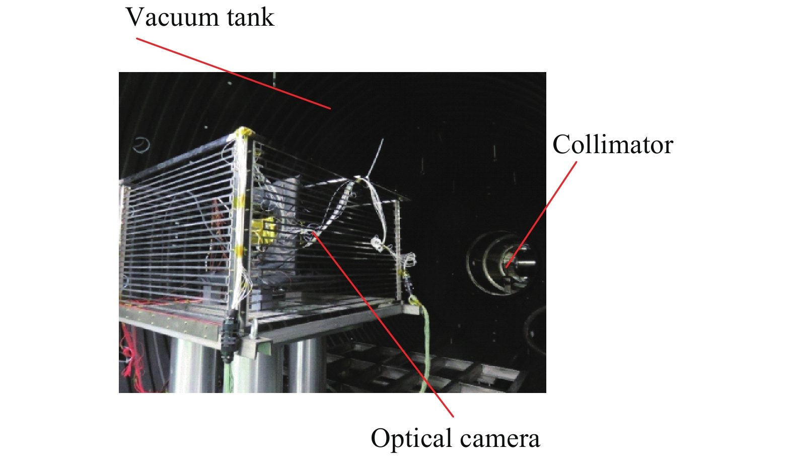
为验证设计结果,测试光学载荷热控调焦系数,需要开展热光学试验。空间光学载荷热光学试验装置由主要由真空罐、试验载荷、试验工装、测温系统、电源系统等组成,如图6所示。黑白条纹等间隔目标板作为平行光管靶标,载荷在各工况平衡后进行成像,以光学系统调制传递函数(MTF)值最高作为最佳焦面位置,试验流程如图7所示。公式(5)计算光学系统MTF,MTF值越大,光学载荷图像质量越好[19]。

Figure 6. Schematic diagram of thermal optical test device

Figure 7. Procedure for thermal optical test
式中:MTF为光学系统调制传递函数;Imax为最大亮度;Imin为最小亮度。
图8中光学载荷热控实施以及光机结构状态与飞行发射状态一致。试验前,采用自准方法对平行光管靶标板进行无穷远位置标定,用高精度莱卡经纬仪检测并调整光学载荷光轴与平行光管同轴。真空罐真空度及热沉温度达到要求后开展试验。

Figure 8. System of thermal optical test
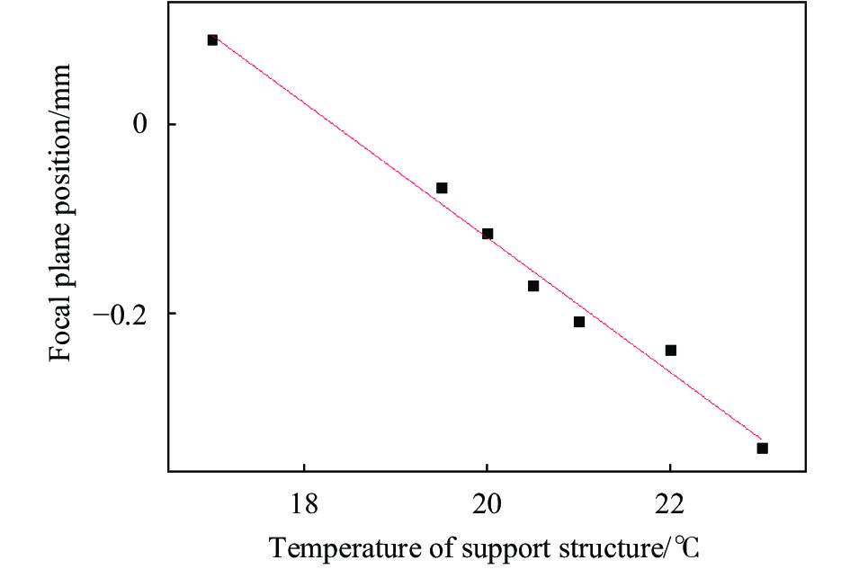
热控调焦系数测试过程如图6所示,光学载荷控温平衡后,调整平行光管靶标位置,光学载荷对不同靶标位置进行成像测试,记录MTF极值时平行光管靶标位置与原始无穷远位置差值
$ \sigma ' $ ,根据公式(5)计算光学载荷焦面离焦量$ \sigma '' $ 。测试支撑结构不同温控条件下的焦面离焦量,即得到热控调焦系数。光学载荷支撑结构进行(20±3) ℃温度范围温度拉偏,其余组部件控温目标为20 ℃,各工况平衡后进行成像测试。该试验7个工况光学载荷测试MTF极值对应的平行光管靶标位置测试结果汇总于表5,图9为测试数据拟合的热控调焦曲线图。试验结果表明,数据线性度较好,热控调焦系数0.071 mm/℃,与理论分析值0.077 3 mm/℃,误差在8%以内,该支撑结构结构设计合理准确可靠,实现了光学载荷调焦功能。
T/℃ $ \sigma ' $/mm $ \sigma '' $/mm MTF 23 −2.05 −0.341 809 028 0.085 8 22 −1.43 −0.238 432 639 0.080 9 21 −1.25 −0.208 420 139 0.083 2 20.5 −1.02 −0.170 070 833 0.081 6 20 −0.69 −0.115 047 917 0.080 8 19.5 −0.4 −0.066 694 444 0.083 3 17 0.54 0.090 037 5 0.081 9 Table 5. Measuring result of thermal optical test

Figure 9. Curve of thermal refocussing
-
“吉林一号”高分03星光学载荷入轨后,开展了热控调焦功能测试。上注光学载荷支撑结构控温门限,获取不同调焦位置处的图像,测试图像动态传函,传函极值位置对应最佳焦面位置。基于刃边法测试动态传函,从含有边缘响应的图像中,提取边缘扩展函数,测量光学载荷在轨传函。实测在轨控温精度为±0.1 ℃,进行了两次热控调焦获得最佳焦面位置,表6为在轨热控调焦结果。
Number Temperature of supporting structure/℃ Dynamic MTF 1 19.4 0.044 2 2 18.4 0.043 6 3 20.0 0.058 8 Table 6. Thermal refocussing test in orbit
-
“吉林一号”高分03星光学载荷采用文中所研究的适用于空间载荷热控调焦的支撑结构形式,减少载荷组件数量,提高了组部件利用率。首先,依据光学系统参数进行调焦精度分析;其次,基于连续拓扑优化中的变密度法进行支撑结构全局优化;最后,介绍了地面试验测试热控调焦系数的方法。通过热光学试验,测试该光学载荷热控调焦系数为0.071 mm/℃,调焦精度为0.014 mm,调焦范围±0.385 mm。“吉林一号”高分03星光学载荷在空间环境下成像质量良好,完成了各项在轨测试,各项指标满足设计要求。该技术的发展为高轻量化、高分辨率、批量化、低成本的空间载荷研制奠定了技术基础。
Design of support structure for space optical payloads with refocusing function (Invited)
doi: 10.3788/IRLA20210476
- Received Date: 2021-07-13
- Rev Recd Date: 2021-08-25
- Publish Date: 2021-10-20
-
Key words:
- space optical payloads /
- supporting structure /
- thermal refocusing /
- thermal optical test
Abstract: High-resolution space optical camera defocused in orbit due to the change of space operational environment, which would affect the image quality. Therefore, refocusing were required by the camera in orbit. In order to meet the requirements of high resolution and lightweight space optical camera, a main support structure with both support and refocusing function was designed. The position of the secondary mirror assembly was adjusted along the optical axis by the precise temperature control of the supporting structure, then the camera can be refocused by the thermal control of the supporting structure. Firstly, the refocusing accuracy was analyzed according to the optical system parameters to determine the design requirements of the support structure; Then, the global optimization of the supporting structure was performed based on the variable density of continuous topology optimization (SIMP); Finally, the thermal optical test was performed to verify the thermal refocusing function and measure the thermal refocusing parameters of the apace camera. The experimental results show that the thermal refocusing parameter of the supporting structure is 0.071 mm/℃, the refocusing accuracy and range are 0.014 mm and ±0.385 mm respectively. The proposed method had been used in the design of "Jilin-1"gf03 satellite which had been tested in orbit, and the focusing accuracy and focusing range meet the design expectations.


 DownLoad: