


-
在面向直线顶管掘进机的诸多导向方法中,激光标靶法以其高精度、高稳定性和低时延等特性被广泛应用于长距离直线顶管或盾构联络通道贯通作业[1-3]。为实现掘进机的精确导向,激光标靶作为导向系统的核心传感装置,须具备优良的光学性能。而应用较为广泛的双屏视觉标靶[4]受限于机械加工精度和装配质量,研制人员难以在生产制造过程中准确获取前、后成像屏的精确位姿关系,其作为位姿测量算法中必不可少的中间参数,需被精确标定。因此,研究双屏视觉标靶成像屏空间位姿的精确标定方法,对提升直线顶管掘进机导向系统的测量性能具有重要意义。
目前,针对相机与空间平面位姿关系标定的问题,高校学者进行了大量研究。王鹤等人[5]以单点激光测距仪和相机的位姿融合为主要研究内容,分别通过光斑坐标和棋盘平面约束建立标定方程,并对位姿参数进行标定。乐英等人[6]根据点云的分布情况对目标物体进行三维空间位置限定,获取独立物体的点云特征。通过区域点云密度分布情况估计具有代表性的局部特征点,将其作为位姿计算的初始值,由D-D(Distance-Density)评价函数获取建立工件坐标系所需要的特征点,通过特征点建立位姿转换矩阵。蒋萌等人[7]对同一场景对应的两幅图像进行立体匹配,求取视差,结合张正友方法对视觉系统进行标定,对选定的特征点进行三维重建,并根据选定的特征点在图像和实际场景中对应的2D-3D位置信息求解目标位姿。宋文松等人[8]利用激光雷达数据的强度信息对点云以中心投影的方式生成灰度图,通过尺度不变特征转换算法对灰度图和相机的图片进行特征点提取和匹配,完成传感器之间的空间位姿标定。上述方法虽解决了相机与单平面位姿关系的标定问题,但无法标定双平面位姿关系的问题依旧存在。由于双屏视觉标靶两个工业相机的公共视场较小,所以无法以相机公共视场作为媒介实现前、后屏位姿关系的标定。
因此,针对双屏视觉标靶前、后感光成像屏位姿关系难以标定的问题,文中提出了一种基于坐标点云的双屏位姿标定方法,该方法具有易于实现、精度高等特点。
-
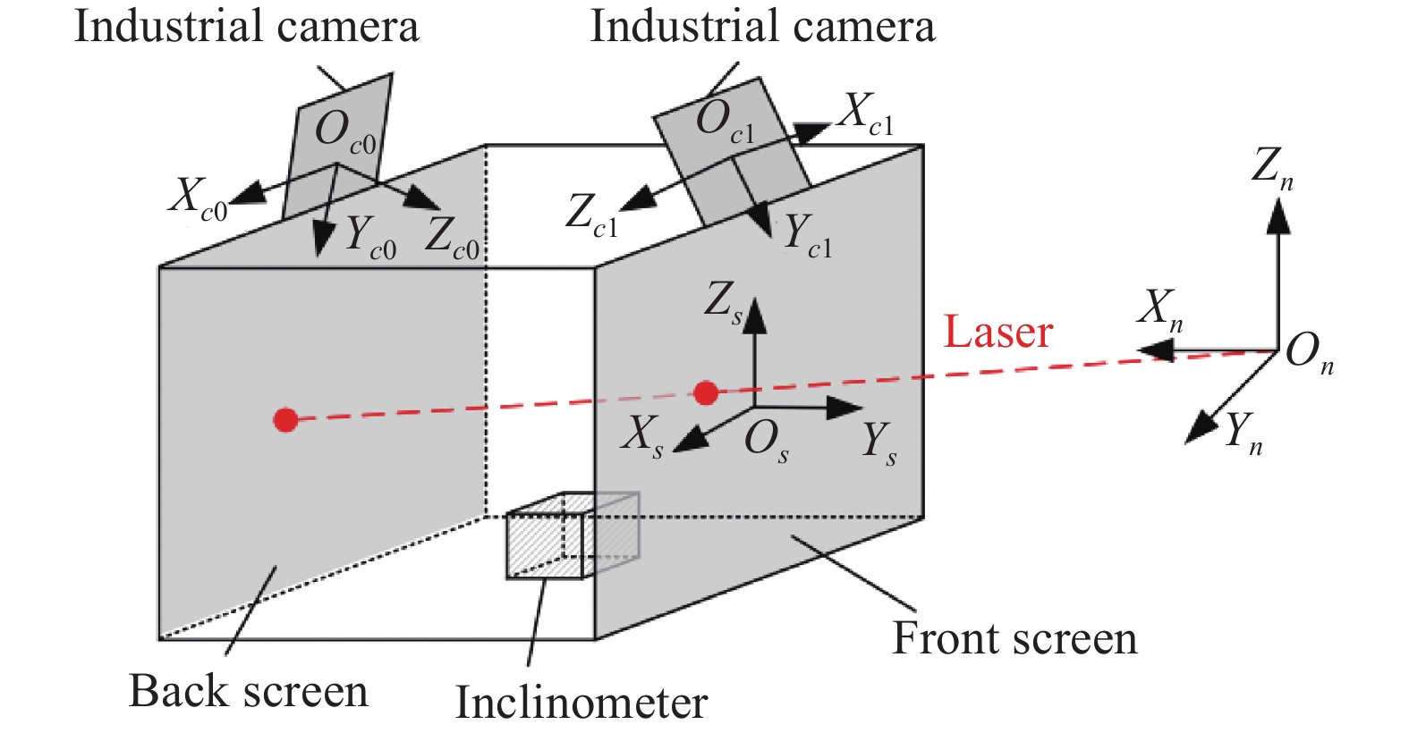
基于双屏视觉标靶的直线顶管掘进机导向系统能够实现顶管机机身姿态的实时精确测量。该系统由一道已知空间指向信息的指示激光和双屏视觉标靶组成,通过姿态测量算法解算指示激光在标靶坐标系和工程坐标系下的单位光矢量,并通过欧拉角计算公式求解坐标系间的旋转矩阵和标靶方位角,进而实现顶管机导向。双屏视觉标靶[4]是直线顶管机导向系统的核心组件,标靶测量模型采用相机对向安装、感光成像屏垂直安装、底部安装双轴倾角仪的结构,其模型示意图如图1所示。其中,标靶靶面由垂直安装的透明感光成像屏(前屏)和黑色磨砂感光成像屏(后屏)组成。两个工业相机分别拍摄前、后屏光斑图像,并提取光斑的图像坐标。双轴倾角仪固定在双屏视觉标靶底端,用于测量双屏视觉标靶的俯仰角和滚转角。其中,相机、感光成像屏、倾角仪为刚性固连关系。

Figure 1. Measurement model of visual target with double screen
-
标靶测量模型中的坐标系有:工程坐标系On-XnYnZn(简称n系)、双屏视觉标靶坐标系Os-XsYsZs(简称s系)、前屏相机坐标系Oc0-Xc0Yc0Zc0(简称c0系)、后屏相机坐标系Oc1-Xc1Yc1Zc1(简称c1系)。上述坐标系的坐标轴方向及原点位置如图2所示。

Figure 2. Definition diagram of coordinate frames
-
设激光束在n系下的单位光矢量为
$\overrightarrow {{{{l}}_{{n}}}}$ ,在s系下的单位光矢量为$\overrightarrow {{{{l}}_{{s}}}}$ ,n系→s系的旋转矩阵为${\boldsymbol{R}}_{{n}}^{{s}}$ ,光矢量之间的转换关系可表示为:在掘进过程中,隧道计划线是已知量,指示激光的作用是复刻隧道计划线,即指示激光与隧道计划线平行。由于直线顶管机掘进线路为直线,指示激光的水平角和垂直角与设计线路一致,且双屏视觉标靶通过已知空间方位信息的指示激光对直线顶管机位姿进行解算。因此,双屏视觉标靶可以应用于直线顶管机导向,指示激光的水平角α、垂直角β为已知量,所以
$\overrightarrow {{{{l}}_{{n}}}}$ 可表示为:$\overrightarrow {{{{l}}_{{s}}}}$ 通过前、后屏上实时光斑的三维坐标进行求解,设前、后屏实时光斑在s系下的三维坐标分别为$P_{{f}}^{{s}}\left( {x_{{f}}^{{s}},y_{{f}}^{{s}},{\textit{z}}_{{f}}^{{s}}} \right)$ 、$P_{{b}}^{{s}}\left( {x_{{b}}^{{s}},y_{{b}}^{{s}},{\textit{z}}_{{b}}^{{s}}} \right)$ ,则$\overrightarrow {{{{l}}_{{s}}}}$ 可表示为:为便于计算,该测量模型三个姿态角的旋转顺序定义为“Y-X-Z”,即n坐标系依次绕Y、X、Z轴旋转。n系的旋转角度分别为方位角θ、俯仰角φ、滚转角γ。其中,由双轴倾角仪获取俯仰角φ、滚转角γ,则旋转矩阵
${\boldsymbol{R}}_{{n}}^{{s}}$ [9]可表示为:根据上述原理可知,标靶方位角θ需要通过
$\overrightarrow {{{{l}}_{{n}}}}$ 、$\overrightarrow {{{{l}}_{{s}}}}$ 求解。由于$\overrightarrow {{{{l}}_{{n}}}}$ 为已知量,所以标靶位姿测量的关键是计算$\overrightarrow {{{{l}}_{{s}}}}$ ,即测量前、后屏实时光斑的空间三维坐标。因此,文中提出了一种基于坐标点云的感光成像屏位姿标定方法,根据坐标点云数据求解前、后屏的位姿关系。 -
在掘进过程中,双屏视觉标靶安装在直线顶管机尾部,并与顶管机机身为稳定的刚体结构。由于直线顶管机的掘进线路为直线,施工时不会出现起伏过大的情况。但是,当顶管掘进机水平/垂直偏差过大时,可能会出现双屏视觉标靶脱靶现象。针对上述情况进行如下分析:
由于顶管掘进机尾部安装空间有限,则双屏视觉标靶的设计尺寸为260 mm×260 mm×344 mm。根据几何关系可知,在不考虑偏差情况下,双屏视觉标靶的最大可旋转的角度为±37.08°(设顺时针旋转为正方向);在考虑到水平偏差的情况下(出现垂直偏差时与本情况类似),设标靶相对于隧道计划线的偏差距离为x(定义向左移动为正方向,x的范围为0~±130 mm),则x与最大可旋转角度±ω之间的函数关系式可表示为:
根据公式可知:随着偏差距离x的不断增大,在确保不脱靶的情况下,双屏视觉标靶可旋转的角度逐渐减小。同时,考虑到顶管掘进机移动速度缓慢,且双屏视觉标靶是用于顶管掘进机导向,当顶管掘进机机身相对于计划线的水平/垂直偏差逐渐增大时,应及时对机身位姿进行调整,以保证现场施工精度,同时减小双屏视觉标靶的脱靶概率。
-
为实现感光成像屏上光斑三维坐标的精确测量,需要对双屏视觉标靶前、后屏的位姿关系进行标定。根据测量模型,前、后屏被划分为n行n列的网格阵列,通过对向安装的两个工业相机分别抓取前、后屏光斑图像的二维坐标,结合全站仪测量前、后屏上光斑的三维坐标,即可构建前、后屏上测量点的图像坐标和三维坐标之间的映射关系[10]。根据每个网格角点坐标的映射关系,获得坐标点云数据,即可完成网格标定,再利用网格索引方法对前、后屏位姿参数进行求解。其中,全站仪坐标系定义为t系。
-
网格标定的流程主要包括以下四个部分。首先,全站仪发射的红外激光作为指示激光,可以分别测量前、后屏实时光斑的三维坐标
$P_{{f}}^{{t}}$ 、$P_{{b}}^{{t}}$ (步骤A)。同时,工业相机拍摄指示激光在感光成像屏上呈现光斑的图像,由该图像获得前、后屏上实时光斑的图像坐标$P_{{f}}^{{c}}$ 、$P_{{b}}^{{c}}$ (步骤B)。在标定过程中,前、后屏被划分为n行n列的网格阵列,由全站仪和工业相机分别获取每个网格角点的三维坐标和二维坐标,并将其作为坐标点云数据(步骤C)。最后,坐标点云数据通过三公共点坐标系转换算法进行坐标转换,将每个网格角点在t系下的三维坐标统一到s系下的三维坐标(步骤D)。根据上述流程对坐标点云数据进行采集、处理,即可实现前、后屏位姿关系的精确标定。网格标定示意图如图3所示。
Figure 3. Schematic diagram of grid calibration
其中,步骤A利用全站仪测量前、后感光成像屏上光斑的三维坐标
$P_{{f}}^{{t}}$ 、$P_{{b}}^{{t}}$ ,坐标测量不确定度小于0.1 mm。步骤B利用工业相机抓取前、后屏光斑图像,根据参考文献[11-15]的相关方法对光斑图像进行预处理和质心提取,由图像获得感光成像屏上光斑的图像坐标$P_{{f}}^{{c}}$ 、$P_{{b}}^{{c}}$ ,光斑质心提取不确定度小于0.5 pixel。步骤C将前后屏划分为n行n列的网格阵列,由步骤A、B获得每个网格角点的三维坐标Pt和图像坐标Pc,并根据坐标数据构建映射关系,即可获取坐标点云数据。步骤D将t系下的三维坐标Pt统一到s系下的三维坐标Ps,则Ps可表示为:式中:
${\boldsymbol{R}}_{{t}}^{{s}}$ 为t系→s系的旋转矩阵,该参数可利用三公共点坐标系转换算法进行解算。三公共点坐标系转换算法原理如图4所示。
Figure 4. Schematic diagram of three common point coordinate frame conversion algorithm
全站仪测量标靶前屏边缘四个角点
$P_{\text{1}}^{{t}}$ 、$P_{\text{2}}^{{t}}$ 、$P_{\text{3}}^{{t}}$ 、$P_{\text{4}}^{{t}}$ 的三维坐标,s系原点坐标为前屏中心点$O_s^t$ ,该点可表示为:式中:x轴的方向矢量为
$\overrightarrow {P_2^tP_1^t} $ 。则s系x坐标轴的单位矢量$\overrightarrow {{X}}$ 可表示为:y轴的方向矢量为垂直于
$\overrightarrow {P_{\text{2}}^{{t}}P_{\text{1}}^{{t}}}$ 、$\overrightarrow {P_{\text{1}}^{{t}}P_{\text{3}}^{{t}}}$ ,且方向由后屏指向前屏,则s系y坐标轴的单位矢量$\overrightarrow {{Y}} $ 可表示为:z轴方向为垂直于x、y轴向上,则s系z坐标轴的单位矢量
$\overrightarrow {{Z}} $ 可表示为:通过三公共点坐标系转换算法建立s系,并解算s系坐标轴的单位方向矢量
$\overrightarrow {{X}} $ 、$ \overrightarrow {{Y}} $ 、$\overrightarrow {{Z}} $ ,则t~s系的旋转矩阵${\boldsymbol{R}}_{{t}}^{{s}}$ 可表示为:式中:
${\boldsymbol{R}}_{{s}}^{{t}}$ 是s系→t系的旋转矩阵。通过上述操作获取前、后屏网格角点2D-3D坐标点云数据后,即可完成前、后屏的位姿标定。 -
根据网格标定原理,c0、c1相机分别抓取前、后屏实时光斑图像,由光斑图像获取前、后屏实时光斑的图像坐标
$P_{{f}}^{{c}}({u_{{f}}},{v_{{f}}})$ 、$P_{{b}}^{{c}}({u_{{b}}},{v_{{b}}})$ ,通过图像坐标索引实时光斑所在网格位置,并结合坐标点云数据将图像二维坐标映射到空间三维坐标,网格索引原理图如图5所示。
Figure 5. Schematic diagram of grid index
设相机抓取实时光斑的图像坐标为
$P_{\text{0}}^{{c}}(u,v)$ ,通过坐标$P_{\text{0}}^{{c}}$ 获取实时光斑所在标定网格位置后,该网格角点的图像坐标$P_{{{lt}}}^{{c}}({u_{{{lt}}}},{v_{{{lt}}}})$ 、$P_{{{rt}}}^{{c}}({u_{{{rt}}}},{v_{{{rt}}}})$ 、$P_{{{lb}}}^{{c}}({u_{{{lb}}}},{v_{{{lb}}}})$ 、$P_{{{rb}}}^{{c}}({u_{{{rb}}}},{v_{{{rb}}}})$ ,其与s系下的三维坐标的映射关系,$P_{{{lt}}}^{{s}}(x_{{{lt}}}^{{s}},y_{{{lt}}}^{{s}},{\textit{z}}_{{{lt}}}^{{s}})$ 、$P_{{{rt}}}^{{s}}(x_{{{rt}}}^{{s}},y_{{{rt}}}^{{s}},{\textit{z}}_{{{rt}}}^{{s}})$ 、$P_{{{lb}}}^{{s}}(x_{{{lb}}}^{{s}},y_{{{lb}}}^{{s}},{\textit{z}}_{{{lb}}}^{{s}})$ 、$P_{{{rb}}}^{{s}}(x_{{{rb}}}^{{s}},y_{{{rb}}}^{{s}},{\textit{z}}_{{{rb}}}^{{s}})$ 的坐标数据,则实时光斑$P_{\text{0}}^{{s}}$ 的三维坐标可以表示为:由上述网格索引方法获取s系下前、后屏实时光斑坐标
$P_{{f}}^{{s}}(x_{{f}}^{{s}},y_{{f}}^{{s}},{\textit{z}}_{{f}}^{{s}})$ 、$P_{{b}}^{{s}}(x_{{b}}^{{s}},y_{{b}}^{{s}},{\textit{z}}_{{b}}^{{s}})$ ,即可解算出s系下的单位光矢量$\overrightarrow {{l_{{s}}}}$ ,并完成标靶位姿的精确测量。 -
为验证该标定方法的准确性,设计了静态测量重复性精度评定实验和绝对测量精度评定实验,实验设备及硬件参数如表1所示。其中,俯仰角和滚转角的测量精度是由倾角仪的精度决定,已知倾角仪出厂精度为0.01°,所以只对方位角进行精度分析即可。
Name Parameter Camera Model:Basler aca1300-60 gm Resolution:1280×1024 pixel Pixel size:5.3 μm×5.3 μm Frame rate:60 fps Total station Model:Leica TS12 Ranging accuracy:2 mm±2 ppm Angle accuracy:2″ Repeatability precision:0.1 mm Inclinometer Angle accuracy:0.01° One dimensional turntable Angle accuracy:2″ Table 1. Parameters of hardware
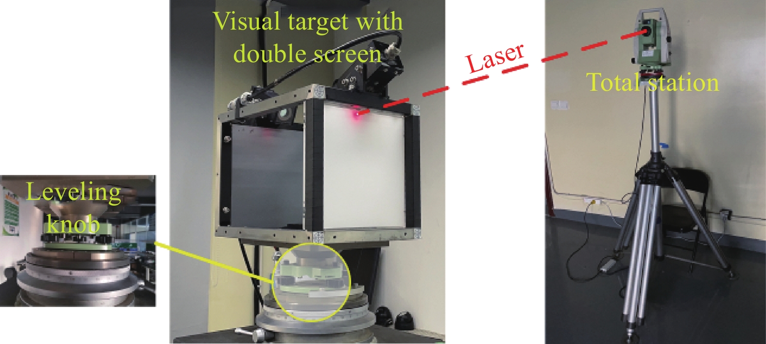
标定过程中,全站仪置于距离双屏视觉标靶9 m位置,利用调平旋钮将双屏视觉标靶调至与水平面平行,分别对前、后感光成像屏进行标定。根据上述标靶结构,全站仪测量网格角点坐标时,由于前屏遮挡后屏,导致全站仪无法直接测量后屏网格角点坐标,则利用全站仪先测量后屏网格角点坐标,再将前屏安装牢固,并测量前屏网格角点坐标,进而完成标定。其中,安装前屏导致的误差可通过调平旋钮和标靶内部倾角仪进行补偿。由于标定网格数量影响索引坐标的准确度和标定效率,所以前、后屏的标定网格分布为50行、50列,从而保证精度和标定效率。实验环境如图6所示。
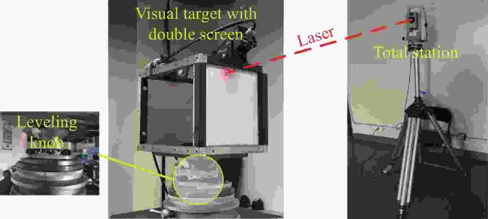
Figure 6. Experimental environment for grid calibration
-
为验证网格索引方法的静态测量重复性精度,该实验利用全站仪发射一束指示激光指向双屏视觉标靶,根据网格索引方法对前屏实时光斑三维坐标进行500次重复测量,测量结果如图7(a)所示;对双屏视觉标靶方位角进行500次重复测量,测量结果如图7(b)所示。

Figure 7. (a) Repeatability accuracy of static measurement of coordinates; (b) Repeatability accuracy of static measurement of heading angle
根据实验数据,测得
$x_{{f}}^{{s}}$ 坐标变化的峰峰值${x_{{{p - p}}}}$ 为0.10 mm,平均值$\overline {x_{{f}}^{{s}}}$ 为0.00 mm,标准差${s_{{x}}}$ 为0.02 mm;$y_{{f}}^{{s}}$ 坐标变化的峰峰值${y_{{{p - p}}}}$ 为0.00 mm,平均值$\overline {y_{{f}}^{{s}}}$ 为0.00 mm,标准差${s_{{y}}}$ 为0.00 mm;$z_{{f}}^{{s}}$ 坐标变化的峰峰值${z_{{{p - p}}}}$ 为0.13 mm,平均值$\overline {z_{{f}}^{{s}}}$ 为0.00 mm,标准差${s_{{z}}}$ 为0.03 mm;方位角测量重复性精度优于0.01°。 -
根据标定原理,该标定方法的精度直接影响标靶方位角测量的精度,而标靶方位角测量的关键在于精确测量实时光斑的三维坐标。因此,为验证该标定方法反算坐标的绝对测量精度,通过分析全站仪测量坐标与双屏视觉标靶反算坐标在X、Y、Z轴方向的偏差,对坐标的绝对测量精度进行评价。为验证该标定方法反算方位角的绝对测量精度,通过分析一维转台实际转动角度与双屏视觉标靶反算方位角变化量的差值,对方位角绝对测量精度进行评价。
-
该实验利用全站仪测量实时光斑在t系下的三维坐标
$P_{\text{1}}^{{t}}$ ,并通过三公共点坐标系转换算法求得s系下的三维坐标$P_{\text{1}}^{{s}}$ ,将其与网格索引实时光斑坐标$P_{\text{0}}^{{s}}$ 求差,则该差值为网格索引方法测量坐标的绝对测量精度。坐标精度评价实验数据如表2所示,表中${d_{{X}}}$ 、${d_{{Y}}}$ 、${d_{{Z}}}$ 表示三维坐标分别在X、Y、Z轴方向的偏差。No. X/mm Y/mm Z/mm ${d_{{X} } }$/mm ${d_{{Y} } }$/mm ${d_{{Z} } }$/mm 1 $P_{\text{0} }^{{s} }$ 24.48 −25.31 79.78 −0.33 0.26 −0.12 $P_{\text{1} }^{{s} }$ 24.15 −25.05 79.66 2 $P_{\text{0} }^{{s} }$ 69.87 −25.30 50.30 −0.94 −0.63 −0.73 $P_{\text{1} }^{{s} }$ 68.93 −25.93 49.57 3 $P_{\text{0} }^{{s} }$ 11.12 −25.69 31.06 −0.43 −0.77 0.51 $P_{\text{1} }^{{s} }$ 10.69 −26.46 31.57 4 $P_{\text{0} }^{{s} }$ −60.41 −25.76 8.43 −0.24 0.18 −0.14 $P_{\text{1} }^{{s} }$ −60.65 −25.58 8.29 5 $P_{\text{0} }^{{s} }$ 53.42 −26.47 −66.79 −0.83 −0.72 −0.34 $P_{\text{1} }^{{s} }$ 52.59 −27.19 −67.13 6 $P_{\text{0} }^{{s} }$ 64.26 −25.73 −43.86 −0.27 −0.17 −0.18 $P_{\text{1} }^{{s} }$ 63.99 −25.9 −44.04 Table 2. Experiment data of coordinate accuracy evaluation
通过坐标精度评价实验数据可知,该方法反算坐标的绝对测量精度优于1 mm。
-
该实验将双屏视觉标靶安装在高精度一维转台上,二者为刚性固连关系,将一维转台的实际转动角度与标靶解算的方位角变化角度作差,即可获得双屏视觉标靶方位角的绝对测量精度。无论双屏视觉标靶与一维转台的旋转中心是否重合,二者旋转角度均一致,并利用调平旋钮和倾角仪可以保证俯仰角和滚转角的测量误差小于0.01°。因此,方位角测量精度评价实验部分不需要考虑一维转台与双屏视觉标靶的初始配准问题。方位角精度评价实验原理如图8所示。
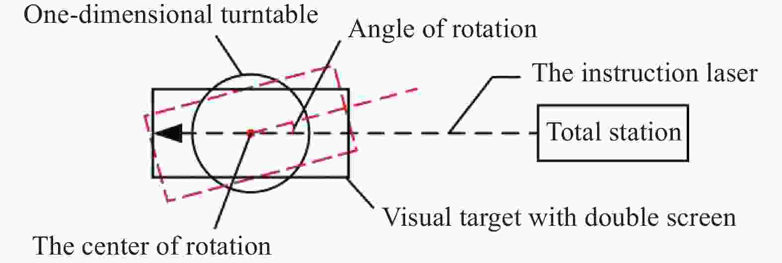
Figure 8. Schematic diagram of heading angle measurement accuracy evaluation experiment
基于上述实验原理,对方位角的绝对测量精度进行评定,数据如图9所示。

Figure 9. Experimental data of heading angle measurement accuracy evaluation
实验结果表明,文中提出的网格标定方法能准确地标定前、后感光成像屏的位姿关系,坐标的绝对测量精度优于1.00 mm,姿态角的绝对测量精度优于0.05°。因此,该标定方法能够对前、后屏位姿关系进行准确快速地标定,并具有较高的精度和稳定性。
-
上述实验利用全站仪、一维转台、相机和倾角仪对双屏视觉标靶感光成像屏的位姿进行标定,并完成了精度测量。在测量过程中,影响系统精度的误差主要来源如表3所示。
Error type Error source Calibration errors of dual screen visual target The error of image recognition The error of total station measurement The error of coordinate system conversion Measurement errors of attitude angles Calculating error of light vector The error of inclinometer measurement Table 3. Errors analysis
(1)图像识别误差。光斑图像由Basler ACA 1300-60 gm工业相机进行采集,分辨率为1280×1024 pixel。若不考虑环境亮度、可见度等原因,图像识别误差约为0.5 pixel。
(2)全站仪测量误差。标定实验采用Leica TS12全站仪,免棱镜坐标测量精度约为2 mm±2 ppm。
(3)坐标系转换误差。该算法经过多次坐标系转换,根据实验可得,坐标系转换误差约为0.01 mm。
(4)激光光矢量解算误差。该算法求解的激光光矢量无法与物理空间绝对一致,则光矢量解算过程会引入误差。根据实验可得,光矢量解算精度约为0.01 mm。
(5)倾角仪测角误差。倾角仪型号为SST-460-30,测角分辨率0.0001°,测角精度为约0.01°。
根据上述误差来源的分析,双屏视觉标靶标定受到图像识别误差、全站仪测量误差、坐标系转换误差的影响,引入该误差源后,双屏视觉标靶坐标测量误差小于0.1 mm。由于全站仪测量误差、光矢量解算误差、倾角仪测量误差等因素造成姿态角的测量误差,在系统误差中加入该误差源后,双屏视觉标靶方位角测量误差小于0.01°。因此,上述误差源对标靶位姿解算影响较小,满足系统精度要求。
-
文中提出一种基于坐标点云的感光成像屏位姿标定方法。该方法将标定平面划分为网格阵列,结合每个网格角点二维图像坐标与三维空间坐标构建2D-3D映射关系,从而得到坐标点云数据。根据三公共点坐标系转换算法将坐标点云数据中的三维坐标统一到标靶坐标系下,进而实现了前、后感光成像屏位姿关系的标定,再通过网格索引方法对同一坐标系下前、后屏实时光斑的三维坐标进行精确测量。文中设计了静态测量重复性精度评价实验和绝对测量精度评价实验,实验结果表明该方法具有较高的坐标测量精度和稳定性。因此,该标定方法可实现前、后感光成像屏位姿关系的精确测量,并具有易于实现、精度高等特点,可用于双屏视觉标靶的标定。
Calibration method and accuracy evaluation of visual target with double screen for straight pipe jacking machine
doi: 10.3788/IRLA20210933
- Received Date: 2022-03-20
- Rev Recd Date: 2022-04-15
- Publish Date: 2022-09-28
Fund Project:
National Key Research and Development Program of China(2019YFB2006100);Tianjin Natural Science Foundation(18JCYBJC88600)
-
Key words:
- vision measurement /
- guidance of pipe jacking machine /
- coordinate point cloud /
- grid calibration
Abstract: Aiming at the problem that it was difficult to calibrate the position and attitude relationship between the front and rear photosensitive imaging screens of visual target with dual-screen, a method for calibrating the position and attitude of the photosensitive imaging screen based on points-cloud was proposed. The front and rear photosensitive imaging screens were respectively divided into grid arrays of n rows and n columns. Combining the image 2D coordinates which were obtained in real time by industrial cameras and the spatial 3D coordinates which were measured by a total station to obtain the 2D-3D mapping relationship of each grid corner point on the photosensitive imaging screen, the coordinate point cloud data were acquired. Next, the 3D coordinates of the coordinate point cloud data are converted to the target coordinate frame according to the three common point coordinate frame transformation algorithm, which can determine the positional relationship between the camera and front/rear photosensitive imaging screen. And then the positional relationship between the front and rear photosensitive imaging screens was solved by the grid indexing method. In order to evaluate the accuracy of target attitude measurement, the static repeatability and the absolute measurement accuracy evaluation experiments were designed. The experimental results show that the static repeatability accuracy of the coordinates is 0.13 mm, the absolute accuracy of the coordinates is 0.93 mm, the static repeatability accuracy of the heading angle is 0.01°, and the absolute accuracy of the heading angle is 0.05°. Therefore, the calibration method can realize the accurate calibration of the pose of two spatial planes, which has the characteristics of simple operation and high precision, and can be used for calibration of visual target with double screen.


 DownLoad: