


-
随着制造业的飞速发展,对发动机气缸、轴承等工件内部形貌测量成为许多工业领域的重要需求[1-2]。根据测量原理的不同,针对内壁的测量方法主要分为接触式测量、非接触式测量。其中接触式测量容易造成内壁损伤[3],通常使用非接触式测量进行工件内壁的检测,基于结构光法、激光扫描法等光电检测法已经成为主要的检测手段。黄战华等[4]搭建了管件内壁的检测系统,该系统由激光位移传感器与轴向爬行机构构成,并提出了管内轮廓还原方法和膛线数据分离方法,通过最小二乘法获取身管内壁参数。激光三维成像法主要利用激光三角位移原理[5]进行测量,其测量场景较为局限,并且激光扫描的检测方法数据采集量大,数据转换环节较为复杂。结构光法具有稳定性好、精度高等特点[6],对深度信息提取准确的优势,其在逆向工程、工件内壁测量领域得到了广泛应用。王颖等[7]采用圆结构光开发出了适用于管道内壁的测量系统,圆结构光由被测物形貌调制,相机采集后,通过解析光条信息得到管道内表面密集点云信息[8],该测量方法结构紧凑、灵活易用,但其标定过程较为复杂,限制了检测范围。丁超等[9-10]提出了基于线结构光对管筒状零件内壁进行三维检测的方法,该方法测量精度较高,但当被测表面曲率较大时,易丢光条信息,导致测量数据不完整。邵新杰[11]提出了一种针对深孔内壁检测系统的位姿标定技术,采用步进电机牵引点云采集系统在工件内部旋转,获取内壁点云数据,其需要采用标准圆筒进行预先标定,通过迭代获取系统的标准位姿参数,普适性较差。
文中提出了一种用于工件内壁测量的面结构光旋转测量方法,利用辅助相机间接获取相机坐标系与旋转平面坐标系间的空间位置关系,将在各个旋转角度获得的局部点云数据转换到旋转平面坐标系下,从而完成对工件内壁的点云拼接。
-
如图1所示,文中测量系统由相机、投影仪、旋转机构及计算机构成。投影仪将条纹编码投射到被测物表面,相机采集经过被测物表面调制的条纹图案,通过相位展开算法获取绝对相位,利用标定信息重建出被测对象的三维形貌。

Figure 1. Model diagram of measurement system
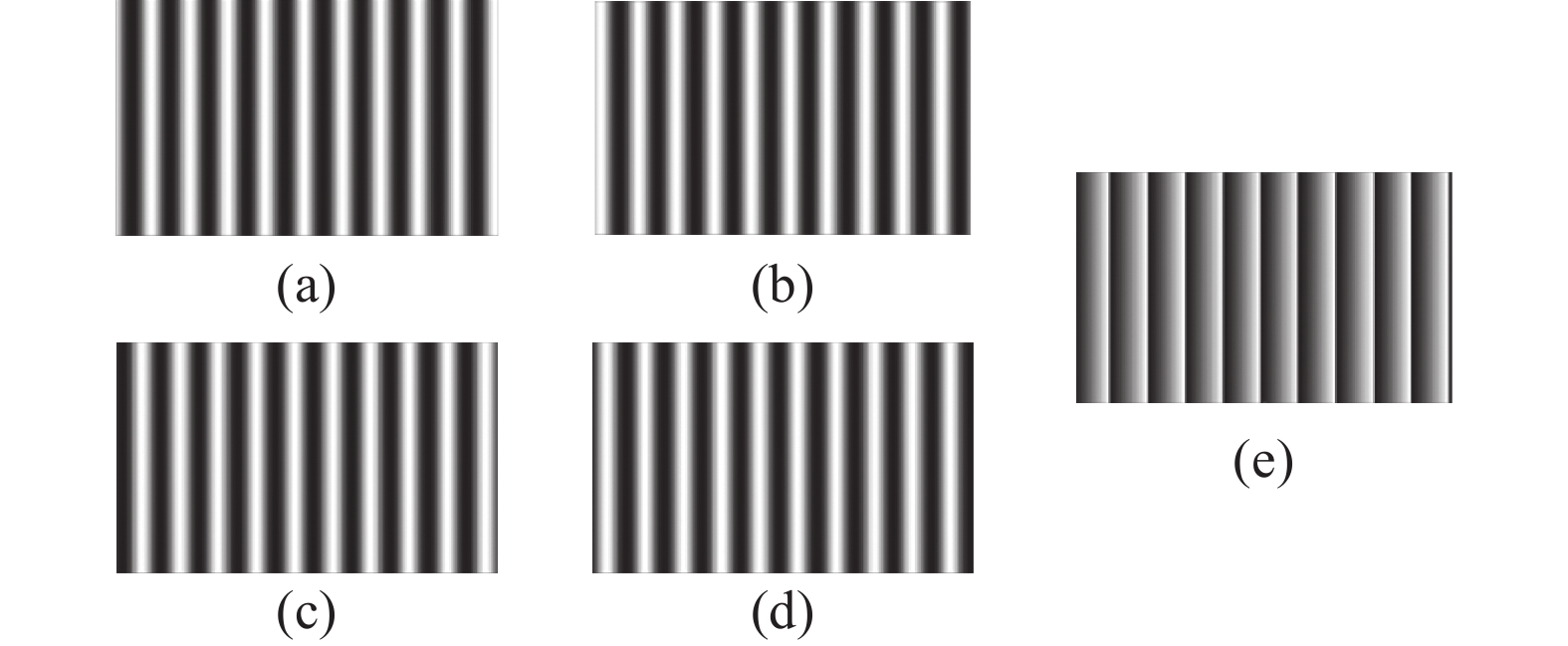
由于四步相移法能够很好地消除检测器偶次谐波(含常数项)的影响[12],文中采用该方法进行相位计算,四步相移法将相移图案每次平移π/2,连续平移三次,光强分布函数如公式(1)所示:
式中:Ii(u,v) 表示第i张相移图上点(u,v)处的强度值;a(u,v)为平均光强值;b(u,v)为调制光强值;
$\phi $ (u,v)为所求的相位值,可得:包裹相位图如图2所示,在一个光栅周期内取值范围为[−π,π]。

Figure 2. Four-step phase-shifting method for solving wrapped phase diagram. (a) Phase shift 0 rad; (b) Phase shift π/2 rad; (c) Phase shift π rad; (d) Phase shift 3π/2 rad; (e) Results of phase shift
-
受采集图像噪声、环境光照等因素影响,格雷码值宽度与相移法的周期宽度并不一致,易产生级次跳变误差[13]。针对该问题,文中采用互补格雷码对获取的包裹相位进行展开。互补格雷码法原理图如图3所示,对前6张格雷码图像和全部7张格雷码图像分别采用格雷解码方式进行相应解码,得到码值分布为k1和k2,通过公式(3)对包裹相位进行展开,得出绝对相位如图4所示。

Figure 3. Schematic diagram of complementary Gray code

Figure 4. Absolute phase diagram
-
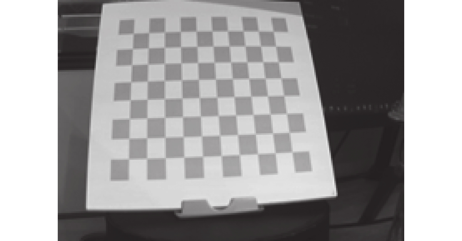
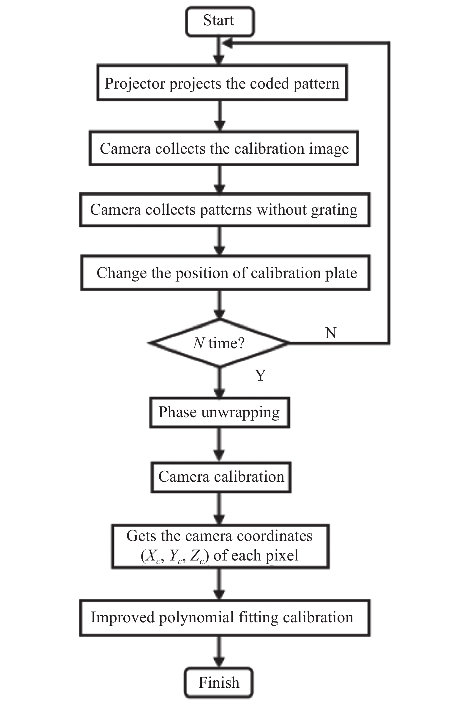
多项式拟合标定过程中,投影图案易受标定板图案的影响产生相位误差,影响标定精度。文中采用灰白棋盘格的多项式拟合法对相机、投影仪进行标定,灰度棋盘格图案如图5所示,标定流程如图6所示。

Figure 5. Checkerboard pattern

Figure 6. Flowchar diagram of camera-projector calibration
对于相机视野中的每一个像素点(u,v),可用多项式方程组表示(Xc,Yc,Zc)与Φ(u,v)间的关系:
式中:N为拟合次数;系数an、bn、cn包含了系统的结构参数。通过多项式拟合建立起多项式系数表。因此,在实物测量中,对于像素坐标系中的任意一点(u,v),根据其绝对相位值Φ(u,v),通过查表法即可获取其对应的相机坐标系下坐标 (Xc,Yc,Zc)。
-
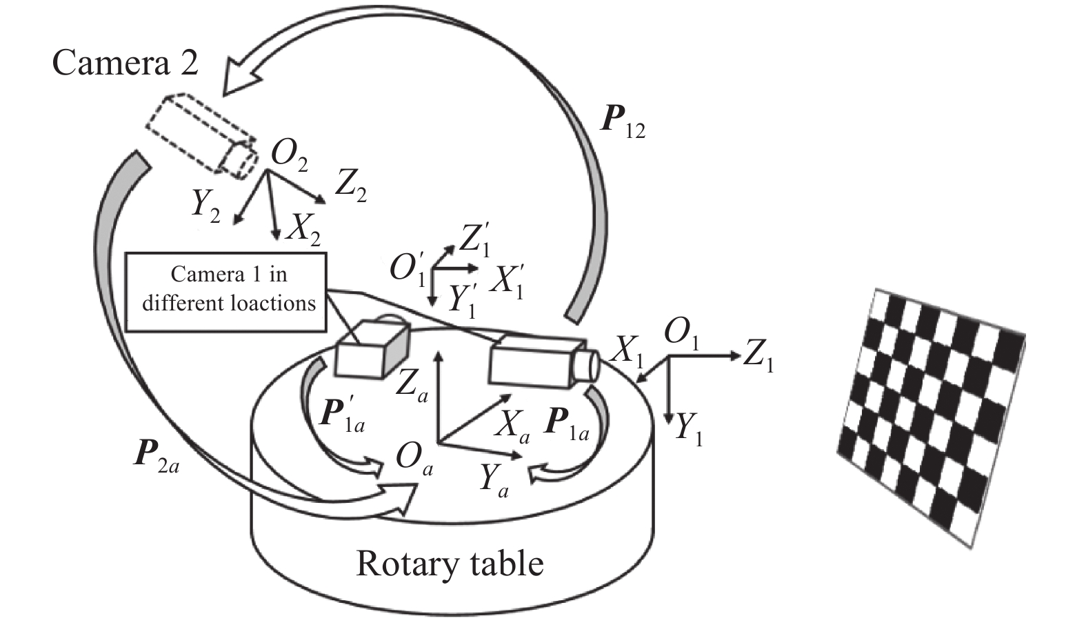
在单一角度下,测量系统只能获取被测工件的局部点云数据,为获取工件的完整形貌信息,通过旋转机构带动相机、投影仪旋转完成多个视角下点云数据采集与拼接。相机坐标系与旋转平面坐标系之间变换关系的准确程度直接决定了多视角点云的拼接精度,测量系统位置关系如图7所示。

Figure 7. Coordinate transformation mode
Oa-XaYaZa为旋转平面坐标系,坐标原点建立在转轴上,在转动过程中,Oa-XaYaZa姿态保持固定,面Oa-XaYa平行于转动平面。
O1-X1Y1Z1为初始位置的相机坐标系,坐标原点在镜头中心,Z1轴为相机光轴,O1-X1Y1为相机成像面。其空间位姿随旋转平面转动而变化,O’1-X’1Y’1Z’1为转动后的相机坐标系,P1a、P’1a分别为初始位置和转动后相机坐标系到旋转平面坐标系的变换矩阵。
设Q1(X1,Y1,Z1,1)为被测工件内壁上一点Q在坐标系O1-X1Y1Z1下的齐次坐标,该点在旋转平面坐标系下的齐次坐标Qa为:
转动过程中,由于坐标系O1-X1Y1Z1相对于坐标系Oa-XaYaZa的位姿发生变化,不同旋转角度对应的P1a不同。因此对P1a的标定是实现点云拼接的关键。
-
文中采用辅助相机法确定旋转平面坐标系并完成相机1坐标系与旋转平面坐标系间的转换,相机2作为辅助,O2-X2Y2Z2表示该相机成像坐标系,该坐标系到Oa-XaYaZa坐标系的齐次变换矩阵表示为P2a:
式中:R2a为坐标系O2-X2Y2Z2和旋转平面坐标系Oa-XaYaZa间的旋转矩阵;T2a为两坐标系间的平移矩阵。求解两矩阵的方法如下所述:
(1)将棋盘格标定板放置于旋转平面上,该标定板共有m个角点,旋转平面旋转t个不同角度,相机2采集t张不同位置的棋盘格图片,棋盘格角点在坐标系O2-X2Y2Z2中的坐标表示为Pki(Xki,Yki,Zki),其中k∈[1,m], i∈[1,t]。
(2)将点Pki(Xki,Yki,Zki)拟合旋转平面ax+by+cz+d=0,以该旋转平面的法向量方向为Za轴方向,以坐标系O2-X2Y2Z2的Z2轴在旋转平面的投影为Ya,建立旋转平面坐标系Oa-XaYaZa,根据坐标系变换关系,得到相机坐标系O2-X2Y2Z2到旋转平面坐标系Oa-XaYaZa的旋转矩阵R2a。
(3)平移向量T2a,即旋转平面坐标系的原点Oa在相机坐标系O2-X2Y2Z2下的坐标值(Xa0,Ya0,Za0):
将棋盘格上的m个角点在相机坐标系O2-X2Y2Z2下的坐标投影到步骤(2)中的拟合平面上。理想情况下,所有角点都位于以原点Oa为圆心的一个空间圆上,为降低相机透视畸变对求解精度的影响,文中采用椭圆拟合提取圆心坐标,椭圆的一般化公式为:
对椭圆中心坐标求均值得到原点Oa的坐标Xa0、Ya0。对所有角点Za轴坐标求均值得到Za0,通过公式(8)求得T2a:
完成旋转平面标定后,将相机1、投影仪固定到旋转平面上,调整相机1使其与相机2视场交集最大,设此处相机1位置为初始位置,获取此时相机1坐标系与辅助标定相机2坐标系间的齐次变换矩阵P12,得:
代入公式(5)得:
设Q’1(X1’,Y1’,Z1’,1)为旋转平面旋转角度α后,坐标系O’1-X’1Y’1Z’1中被测物表面上一点Q’的齐次坐标,可得该点在旋转平面坐标系下的齐次坐标Q’a为:
式中:P’12为转动角度α时,相机1、2间齐次变换矩阵,得:
其中,Ra为转动角度α时,对应的旋转矩阵为:
将公式(12)代入公式(11)得:
-
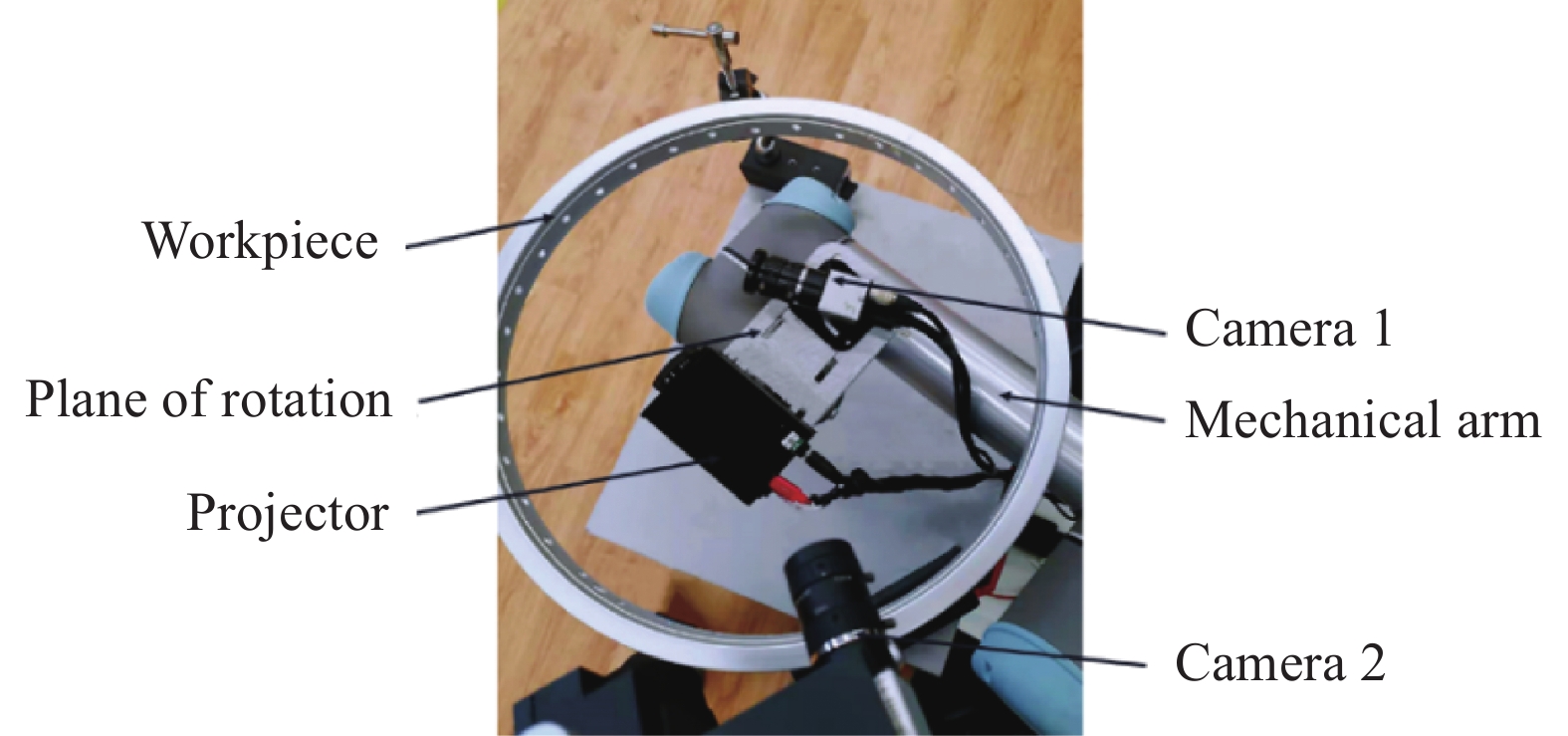
如图8所示,实验平台包含一台工业相机(分辨率为1280×1024,帧率为75 fps),一台数字投影仪(分辨率为1280×720 pixel,帧率为60 fps)及一台六轴机械臂(UR5)组成。以带有通孔的铝制环形工件作为被测对象,采用7位互补格雷码,其中,第6位格雷编码条纹宽度为20 pixel。四步相移法采用光栅条纹周期节距为20 pixel。相机与工件内壁间距离约为170 mm,有效视场宽度约为150 mm,实验过程如下:

Figure 8. Composition of experimental system
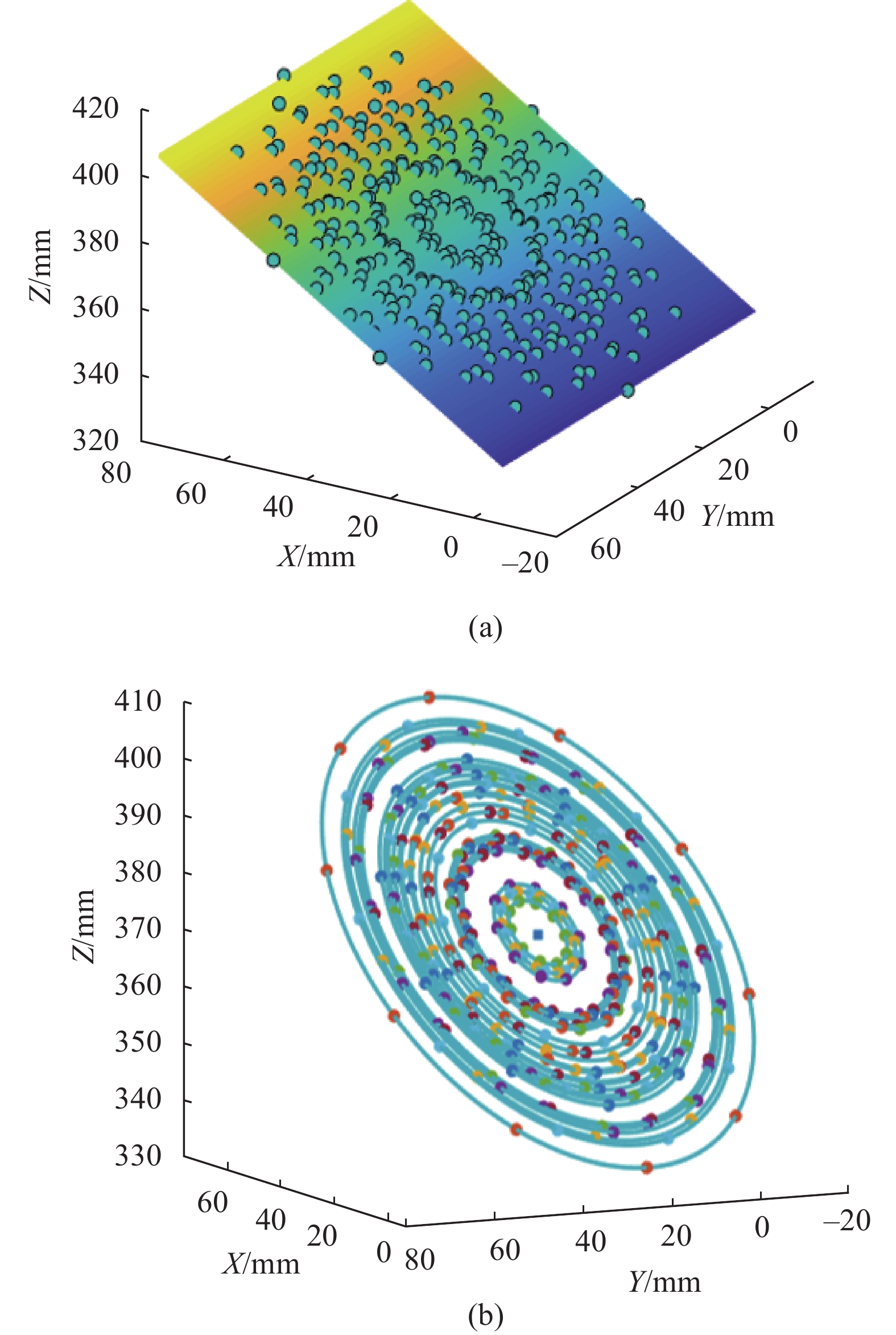
(1) 将标定板置于旋转平面上,每转动30°,辅助相机2(分辨率为1280×1024,帧率为75 fps)采集1张图像,共采集12张标定图像,拟合面Oa-XaYa和转动平面坐标系原点(Xa0,Ya0,Za0),结果如图9所示,根据公式(6),获取相机2坐标系与转动平面坐标系的变换矩阵P2a,表1为相机2内参与旋转平面坐标系标定结果。

Figure 9. Image of turntable calibration fitting. (a) Checkerboard corners fitting the plane; (b) Checkerboard corners fitting the ellipse
Intrinsic parameters
of camera 1Values Parameters
of camera 1, 2Values fu1 1693.1212 R12 0.8794 0.2368 −0.4131
0.0790 0.7830 0.6170
0.4695 −0.5752 0.6700fv1 1684.9189 u01 617.9206 v01 572.1863 T12 203.2638 −154.7710 −156.0094 k11 0.0165 Table 1. Calibration results of auxiliary camera 2 and turntable
(2) 将相机1、投影仪固定于旋转平面上,对相机1、2进行标定,获取两相机坐标系间的变换矩阵P12。表2为相机1内参和相机1、2坐标系的标定结果。
Intrinsic parameters of camera 2 Values Calibration parameters of turntable Values fu2 1737.9983 R2a −0.0023 −0.0312 0.9951
0.9973 −0.0741 0.0102
0.0741 0.9968 0.0313fv2 1727.9421 u02 639.7128 v02 477.7666 T2a −338.5816 6.4040
−146.7043k12 −0.0179 Table 2. Coordinate transformation relationship of camera 1 internal reference and camera 1, 2
(3) 采用1.3节灰白棋盘格多项式拟合标定方法,采集标定板25个不同位置的光栅及无光栅图像。根据公式(4)获取多项式系数,其中拟合次数N=3。
为了评估文中点云拼接方法的精度,文中对图8中的铝制工件进行了重建:
(1) 将该工件固定到测量位置,投影仪投射条纹编码图案到工件内壁,同时相机采集变形的条纹图像。
(2) 对采集到的条纹图像进行解相处理,获取每个像素的绝对相位值,得出该工件内壁的点云数据。
(3) 通过公式(14)对点云拼接,重建工件内壁三维模型重建结果及细节如图10(a)、(b)所示,相邻角度获取的点云重叠处过渡光滑。取工件内壁圆周4个特征点1、2、3、4的两两间距来对实际数据与测量数据进行比较。表3为4个特征点间连线的实际值与测量值之间的对比。测量值与实际值的平均误差为0.048 mm,标准偏差为0.056 mm,满足拼接精度要求。

Figure 10. Splicing result. (a) Partial splicing details; (b) Global stitching result
Line of measurement Actual value Measured value Error Line12 244.0113 243.9583 0.053 Line13 345.0742 345.0313 0.043 Line14 243.9514 244.0154 −0.064 Line23 244.0342 243.9902 0.044 Lline24 344.9786 345.0336 −0.055 Line34 243.9465 243.9775 −0.031 Average error 0.048 Standard deviation 0.056 Table 3. Comparison between actual value and measured value
-
文中针对某些工件内部形貌的三维测量需求,提出了一种基于面结构光视觉的旋转重建方法。建立了点云拼接的数学模型,并通过辅助相机标定法解决了在工件内壁测量中的点云拼接问题。实验结果表明,文中方法可对工件内壁进行有效测量,拼接平均误差不大于0.05 mm,为复杂内壁结构工件的三维形貌测量提供了有益参考。
Research on rotating splicing of point cloud in workpiece wall based on surface structured light
doi: 10.3788/IRLA20210952
- Received Date: 2021-12-10
- Rev Recd Date: 2022-03-25
- Publish Date: 2022-09-28
Fund Project:
National Key Research and Development Program of China (2018YFB1306900);National Natural Science Foundation of China (U1813222,U20 A20283)
-
Key words:
- optical measurement /
- workpiece inner surface /
- point cloud splicing /
- rotating reconstruction
Abstract: In order to solve the problem of limited internal space and difficult measurement of some workpiece, a point cloud rotating splicing method based on surface structured light was proposed. The reconstruction method of single field of surface structured light was introduced in this paper. The absolute phase value was obtained by combining four-step phase shift and complementary Gray code, and the camera and projector were calibrated by polynomial fitting method. The point cloud registration was studied based on the rotation plane of the wrist joint at the end of the manipulator. A calibration method based on the auxiliary camera was proposed, and the transformation relationship between the camera imaging coordinate system and the rotation plane coordinate system was given. The experimental results show that the method is suitable for measuring the inner wall of workpiece, and the average error of splicing is less than 0.05 mm, which meets the requirements of practical application.


 DownLoad: