


-
激光光束广泛应用于微纳加工、卫星通信、精密测量、显微成像等领域[1-2],对于光束指向稳定性具有较高要求。激光器内部温漂、机械结构变形、光学元件热效应等致使出射光束指向失调,光斑在目标靶面发生漂移。
为抑制光束指向失调,需建立光束指向调控系统,使用位置敏感探测器(Position Sensitive Detector,PSD)等检测反映光束指向失调的靶面光斑位置偏差量,据此驱动执行机构转动,改变光束指向以补偿偏差。机械式驱动机构主要有使用快速反射镜、扫描振镜的反射式方案[3-4]、使用旋转双棱镜的透射式方案[5-6],非机械式驱动机构则有基于声光偏转技术、液晶偏转技术、电光偏转技术等方案[7]。快速反射镜响应速度快、动态滞后误差小,应用相对广泛[8]。
单个快速反射镜系统可矫正光束角度偏差,常用于激光通信平台[9]等。由于仅有一个镜面控制对象,镜面偏转角与光斑位置偏移为明确的线性关系,PID、自适应控制等是常用方法[10-11]。单一镜面亦导致其无法应对入射光束存在较大位置失调的情况[12]。双快速反射镜光束指向调控系统具有两个独立偏转的反射镜面,可同时矫正光束位置及角度偏差,两镜面具有不同的偏转角时,光束传播的角度及位置均发生改变,光刻机照明等高精密光学设备需配备此类光束指向调控系统以实现高精度光束指向稳定[13-14]。两面快速反射镜的联合控制引入耦合问题[15],根据探测器检测的光斑位置偏移量难以直接解算光束指向调控所需的镜面偏转角,快速反射镜偏转控制依赖于实验数据的线性耦合矩阵[13,16]。目前,透射式方案的棱镜转角正反向问题已有较多理论分析[17-18],从三维方向分析双快速反射镜系统镜面偏转角与光斑位置偏离的关联,有助于厘清双快速反射镜系统耦合问题的实质,为前述线性拟合处理提供理论依据。
基于此,文中建立双快速反射镜光束指向调控系统理论模型,分析了正向求解快速反射镜偏转角所面临的耦合问题,推导了小角度偏转角与光斑位置偏差的近似线性关系,提出基于浅层神经网络的偏转角快速求解方法。仿真实验表明,所述方法可快速、有效地解算光束指向调控所需的双快速反射镜偏转角。
-
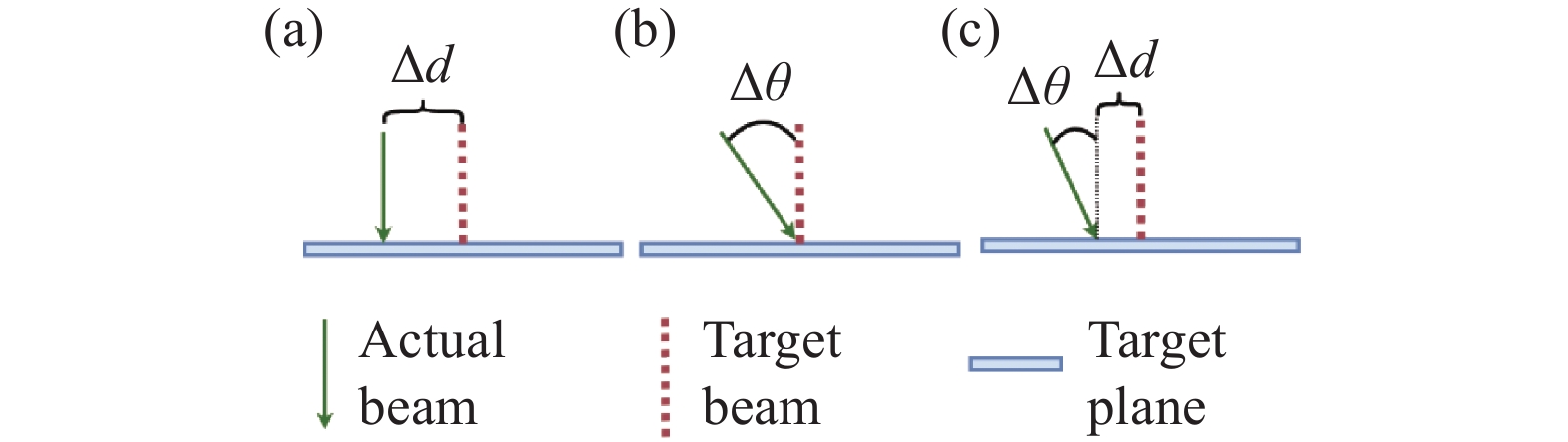
光束指向失调可分为位置失调、角度失调、位置及角度耦合失调等情况,图1(a)~(c)所示为三种光束指向失调情况的示意图。

图 1 (a) 光束位置失调、(b) 光束角度失调及(c) 光束位置及角度耦合失调示意图
Figure 1. Schematic diagrams of (a) displacement of position, (b) displacement of angle and (c) displacement of position and angle
图2所示为双快速反射镜光束指向调控系统示意图,具有双分支光路分别测量位置失调量与角度失调量,图中FSM1、FSM2为快速反射镜,BS1、BS2为分束镜,M1为反射镜,Lens1、Lens2为薄透镜,PSD1、PSD2为探测器。当光束存在指向失调时,主光束经过分光镜产生的子光束在探测器上形成的光斑偏离探测器中心点。
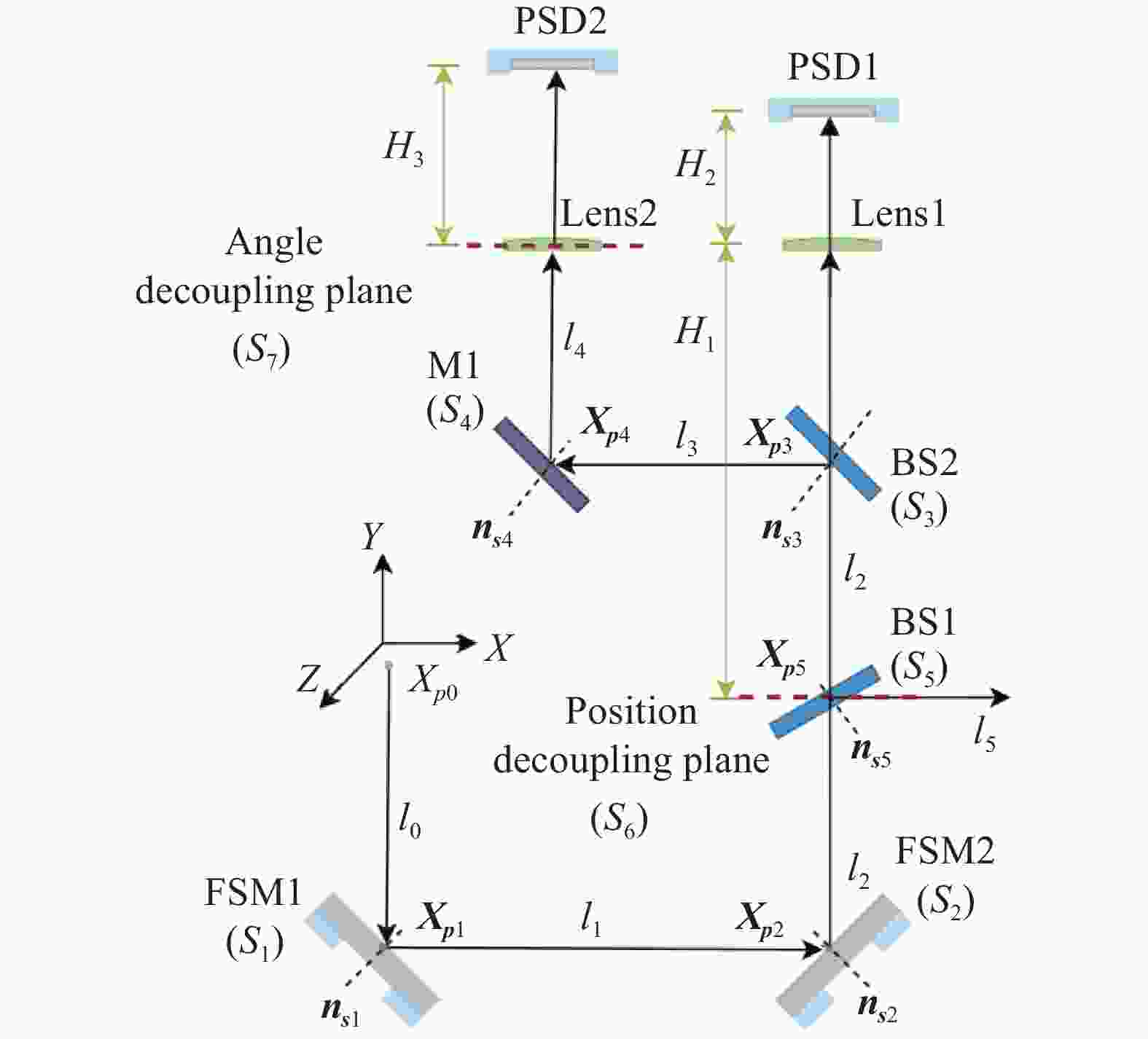
图 2 基于双快速反射镜的光束指向调控系统示意图
Figure 2. Schematic diagram of beam direction control system based on dual fast steering mirrors
面向均值气层环境、短距离光束传输展开讨论,忽略大气湍流、光束发散等微弱影响,光束视为沿直线传播且处于近轴范围,光学元件(反射镜、分束镜等)及探测器视作刚体,其与光束接触面视为三维平面。
-
设有平面$ s $,其具有固定点$ {\boldsymbol{X}}_{\boldsymbol{s}} $及法向量$ {\boldsymbol{n}}_{\boldsymbol{s}} $,自$ {\boldsymbol{X}}_{0} $点出射、拥有方向向量$ \boldsymbol{d} $的光束$ l $与平面$ s $相交,产生质心点为$ {\boldsymbol{X}}_{\boldsymbol{p}} $的光斑,光束$ l $与平面$ s $非平行,则交点$ {\boldsymbol{X}}_{\boldsymbol{p}} $满足以下约束方程:
$$ \begin{array}{c}{{\boldsymbol{X}}}_{{\boldsymbol{p}}}={\left[\begin{array}{c}{{{\boldsymbol{n}}}_{{\boldsymbol{s}}}}^{{\mathrm{T}}}\\ \left[{{\boldsymbol{d}}}_{\times }\right]\end{array}\right]}_{left}^{-1}\left[\begin{array}{c}{{{\boldsymbol{n}}}_{{\boldsymbol{s}}}}^{{\mathrm{T}}}{{\boldsymbol{X}}}_{s}\\ \left[{{\boldsymbol{d}}}_{\times }\right]{{\boldsymbol{X}}}_{0}\end{array}\right]\end{array} $$ (1) $$ \begin{array}{c}{{\boldsymbol{d}}}_{\times }=\left[\begin{array}{ccc}0& -{x}_{d}& {y}_{d}\\ {z}_{d}& 0& -{z}_{d}\\ -{y}_{d}& {x}_{d}& 0\end{array}\right]\end{array} $$ (2) 式中:平面$ s $法向量${\boldsymbol{n}}_{\boldsymbol{s}}=[{{A}}_{{n}_{s}},{{B}}_{{n}_{s}},{{C}}_{{n}_{s}}]^{'}$;固定点$ {\boldsymbol{X}}_{\boldsymbol{s}}= [{x}_{{X}_{s}},{y}_{{X}_{s}},{z}_{{X}_{s}}]^{{'}} $;光束$ l $方向向量$ \boldsymbol{d}=[{x}_{d},{y}_{d},{z}_{d}]^{'} $;点$ {\boldsymbol{X}}_{0}= [{x}_{{X}_{0}},{y}_{{X}_{0}},{z}_{{X}_{0}}]^{'} $。光束$ l $在平面$ s $产生反射,反射后的出射光束$ l^{'} $过光斑交点$ {\boldsymbol{X}}_{\boldsymbol{p}} $且具备方向向量$ \boldsymbol{d}^{'} $,方向向量$ \boldsymbol{d}^{'} $满足三维反射变换:
$$ \begin{array}{c}{{\boldsymbol{d}}}^{{'}}=\left(E-2{{\boldsymbol{n}}}_{s}{{{\boldsymbol{n}}}_{s}}^{{\mathrm{T}}}\right){\boldsymbol{d}}\end{array} $$ (3) 对于图2所示的光路结构,分束镜视为厚度可忽略的薄透镜,设定输入光束$ {l}_{0} $原始状态信息(出射点$ {\boldsymbol{X}}_{{\boldsymbol{p}}_{0}} $与方向向量$ {\boldsymbol{d}}_{0} $), 可顺次得到光束与快速反射镜FSM1及FSM2、分束镜BS2、反射镜M1的交点${\boldsymbol{X}}_{{\boldsymbol{p}}_{{i}}}$及出射光束$ {l}_{i} $的方向向量${\boldsymbol{d}}_{{i}}$($ i=\mathrm{1,2},\mathrm{3,4} $):
$$ \begin{array}{c}{{\boldsymbol{X}}}_{{p}_{i}}={\left[\begin{array}{c}{{{\boldsymbol{n}}}_{{s}_{i}}}^{{\mathrm{T}}}\\ \left[{{{\boldsymbol{d}}}_{i-1}}_{\times }\right]\end{array}\right]}_{left}^{-1}\left[\begin{array}{c}{{{\boldsymbol{n}}}_{{s}_{i}}}^{{\mathrm{T}}}{{{\boldsymbol{X}}}_{s}}_{i}\\ \left[{{{\boldsymbol{d}}}_{i-1}}_{\times }\right]{{\boldsymbol{X}}}_{{p}_{i-1}}\end{array}\right]\end{array} $$ (4) $$ \begin{array}{c}{{\boldsymbol{d}}}_{i}=\left(E-2{{\boldsymbol{n}}}_{{s}_{i}}{{{\boldsymbol{n}}}_{{s}_{i}}}^{{\mathrm{T}}}\right){{\boldsymbol{d}}}_{i-1}\end{array} $$ (5) 式中:${{\boldsymbol{X}}_{\boldsymbol{s}}}_{{i}}$为对应镜面的中心固定点位置坐标;${\boldsymbol{n}}_{{\boldsymbol{s}}_{{i}}}$为对应镜面的法向量。
对于具有法向量$ {\boldsymbol{n}}_{\boldsymbol{f}} $的快速反射镜平面,围绕自身旋转轴$ \boldsymbol{\mu } $偏转角度$ \theta $形成的新法向量$ {{\boldsymbol{n}}_{\boldsymbol{f}}}^{{'}} $,可使用罗德里格旋转公式描述为:
$$ \begin{array}{c}{{{\boldsymbol{n}}}_{f}}^{{'}}={{{\boldsymbol{S}}}_{\mu }{\boldsymbol{n}}}_{f}\end{array} $$ (6) 式中:$ {\boldsymbol{S}}_{\boldsymbol{\mu }} $为旋转矩阵。两轴快速反射镜可绕轴$ \boldsymbol{\mu } $及$ \boldsymbol{\upsilon } $旋转,即
$$ \begin{array}{c}{{{\boldsymbol{n}}}_{f}}^{{'}}={{{{\boldsymbol{S}}}_{\upsilon }{\boldsymbol{S}}}_{\mu }{\boldsymbol{n}}}_{f}\end{array} $$ (7) -
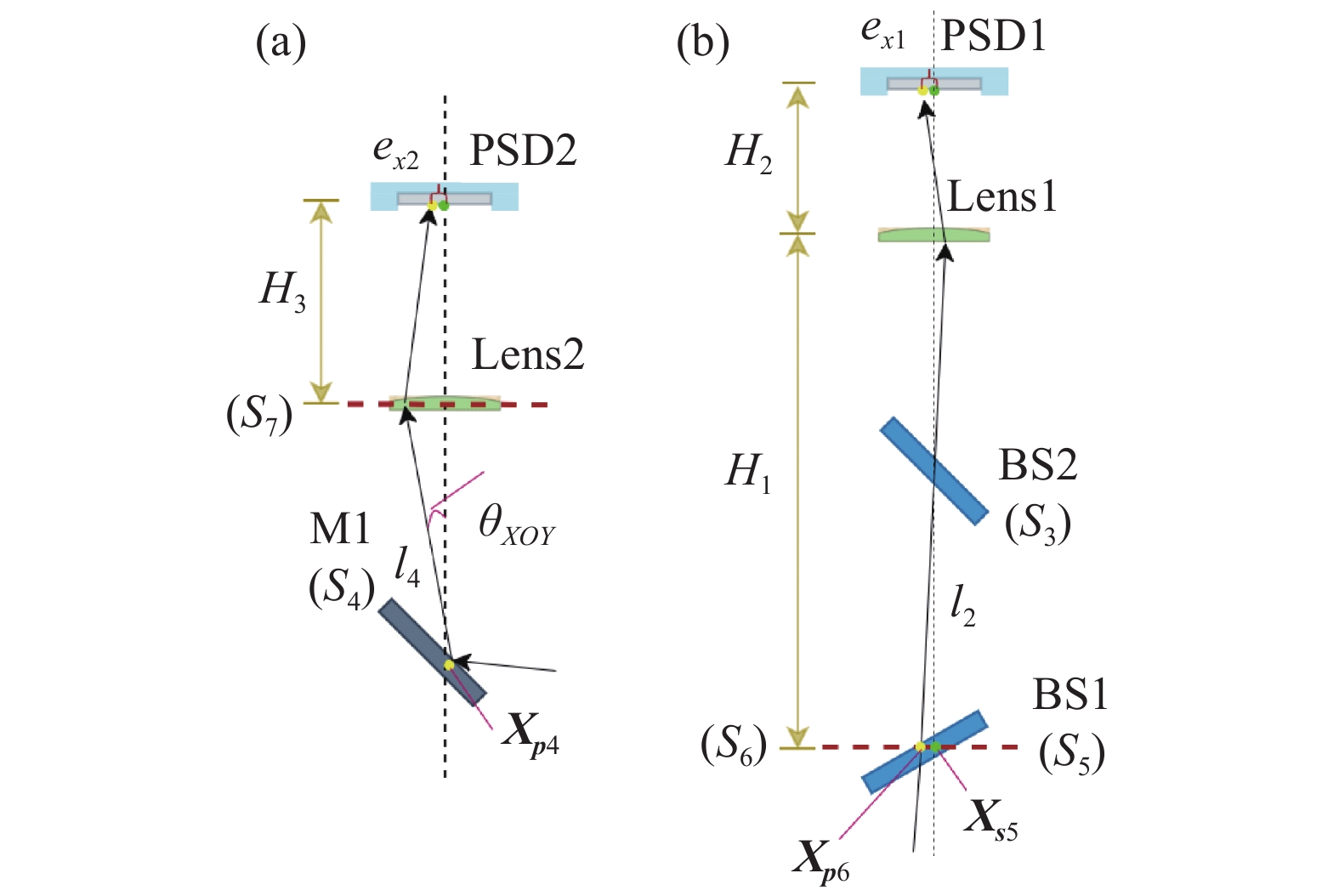
使用双分支光路测量光束指向,对光束的位置失调量及角度失调量进行解耦,如图2所示。分束镜BS1、BS2、凸透镜Lens1及探测器PSD1组成位置偏差探测光路,Lens1焦距满足高斯公式($ {{f}_{1}}^{-1}={{H}_{1}}^{-1}+ {{H}_{2}}^{-1} $),光束成像于后方探测器平面。反射镜M1、凸透镜Lens2及探测器PSD2组成角度偏差探测光路,Lens2焦距$ {f}_{2}={H}_{3} $,光束聚焦于后方探测器平面。光束指向失调时,XOY平面位置偏差探测光路与角度探测光路状况如图3所示。
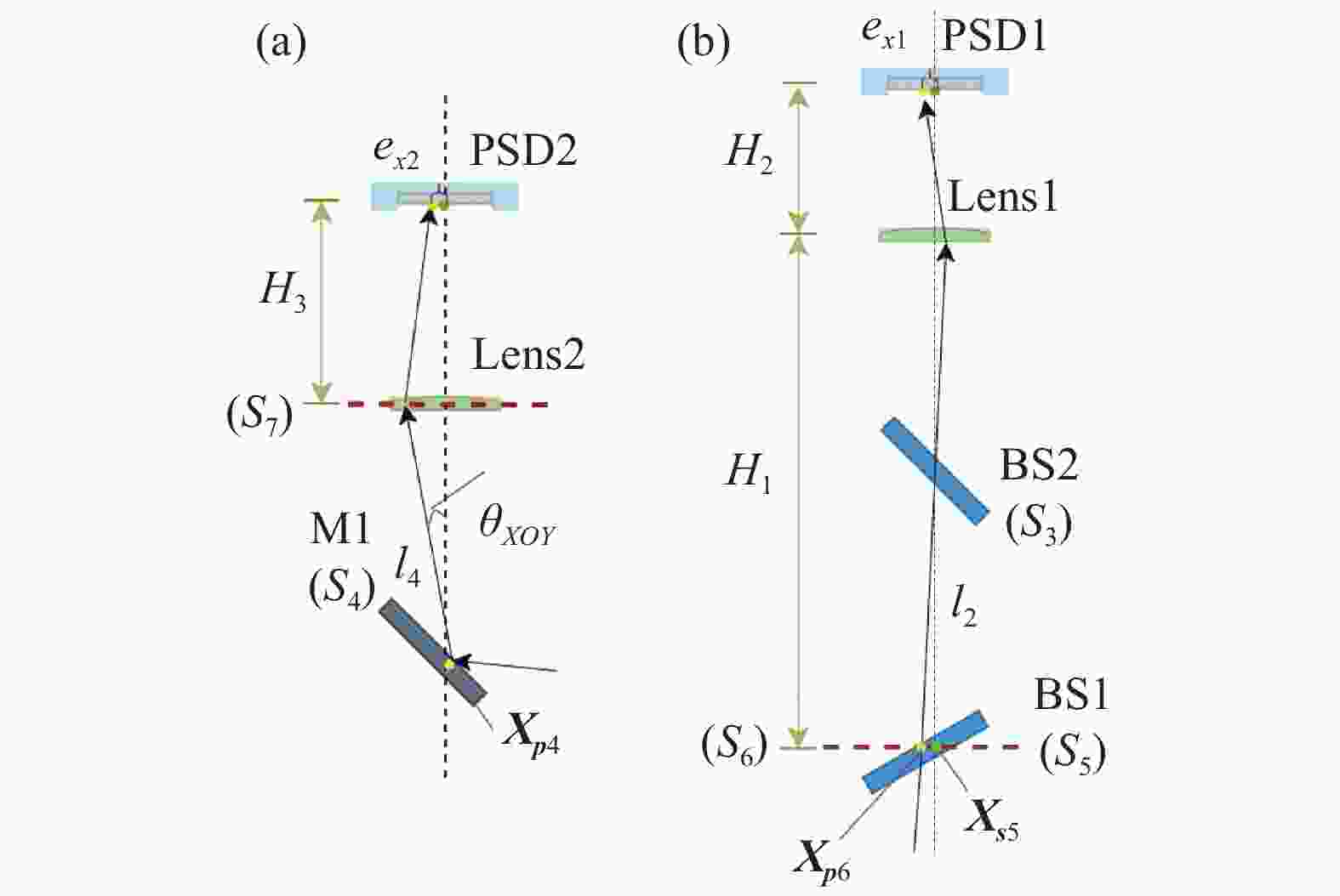
图 3 (a) 角度和(b) 位置解耦光路
Figure 3. Example of (a) angle and (b) position decoupled optical path
光斑质心位置与探测器PSD1的偏差可使用下式表示:
$$ \begin{array}{c}\left[\begin{array}{c}{e}_{x1}\\ {e}_{z1}\end{array}\right]=m\left[\begin{array}{c}{x}_{{X}_{{s}_{5}}}-{x}_{{X}_{{p}_{6}}}\\ {z}_{{X}_{{s}_{5}}}-{z}_{{X}_{{p}_{6}}}\end{array}\right]\end{array} $$ (8) 式中:$ m $为放大率,$ m=-\dfrac{{H}_{2}}{{H}_{1}} $;${\boldsymbol{X}}_{{\boldsymbol{p}}_{6}} $=${\left[\begin{array}{c}{{{\boldsymbol{n}}}_{position}}^{{\mathrm{T}}}\\ \left[{{{\boldsymbol{d}}}_{2}}_{\times }\right]\end{array}\right]}_{left}^{-1}\cdot \left[\begin{array}{c}{{{\boldsymbol{n}}}_{position}}^{{\mathrm{T}}}{{{\boldsymbol{X}}}_{{\boldsymbol{s}}}}_{5}\\ \left[{{{\boldsymbol{d}}}_{2}}_{\times }\right]{{\boldsymbol{X}}}_{{{\boldsymbol{p}}}_{2}}\end{array}\right]$。
光斑质心位置与探测器PSD2中心的偏差可使用下式表示:
$$ \begin{array}{c}\left[\begin{array}{c}{e}_{x2}\\ {e}_{z2}\end{array}\right]={H}_{3}\left[\begin{array}{c}{\theta }_{XOY}\\ {\theta }_{YOZ}\end{array}\right]={H}_{3}\left[\begin{array}{c}{\rm{actan}}\dfrac{{x}_{{d}_{4}}}{{y}_{{d}_{4}}}\\ {\rm{arctan}}\dfrac{{z}_{{d}_{4}}}{{y}_{{d}_{4}}}\end{array}\right]\end{array} $$ (9) 式中:$ {\theta }_{XOY} $、$ {\theta }_{YOZ} $为光束$ {l}_{4} $与凸透镜Lens2主光轴在XOY、YOZ平面投影的夹角,通过光束$ {l}_{4} $的方向向量$ {\boldsymbol{d}}_{4} $计算。PSD探测器通过不等值端口电流反映光斑与其中心的偏离情况,视$ \left[{e}_{x1},{e}_{z1}\right]{'} $、$ \left[{e}_{x2}{,e}_{z2}\right]{'} $等同于探测器传感电信号。光束经透镜聚焦于PSD2,光斑位置偏差不受光束位置偏移影响,实现了光束位置失调量与角度失调量的解耦测量。特别的,光路具有可逆性,基于光斑位置偏差反向迭代公式(4)~(7)即可求得初始光束$ {l}_{0} $原始状态,即由后端探测器信号$ \left[{e}_{x1,}{e}_{z1},{e}_{x2},{e}_{z2}\right]{'} $理论上可确定唯一的初始光束$ {l}_{0} $。
综上,可建立光束指向调控过程理论模型,预设初始光束状态及光学元件位置参数,主动输入为FSM1、FSM2绕轴偏转角$ \boldsymbol{\theta }=[{{\theta }_{1}}_{\mu },{{\theta }_{1}}_{v},{{\theta }_{2}}_{\mu },{{\theta }_{2}}_{v}] $。${\boldsymbol{\theta}}$更新后,根据公式(7)同步更新快速反射镜法向量,并结合公式(4)~(9)顺次更新光束与光学元件交点及探测器输出的光斑位置偏差值$ \left[{e}_{x1,}{e}_{z1},{e}_{x2},{e}_{z2}\right]{'} $,该模型反映了出射、入射光束与双快速反射镜偏转角的数学关系。
-
根据上述理论模型可建立仿真实验环境。理想无误差条件下,在图2所示光路的世界坐标系原点垂直入射光束,在探测器PSD1、PSD2处形成的光斑应恰好位于平面中心位置,即光斑位置偏差值为0。受有限字长限制,仿真过程已引入量化误差,以双精度浮点值模拟初始光束无位移及指向失调的入射状态,产生的光斑位置偏差值小于2e-10 μm,视为可忽略不计的系统误差。
在图2所示的系统光路中,分束镜与探测器为固定安装,其平面固定点和法向量固定不变;FSM1及FSM2固定安装且镜面可绕轴摆动。为使得仿真模型接近真实工况,在快速反射镜加入有限分辨率约束及随机时变误差项。随机时变误差用以模拟快速反射镜摆动的随机噪声,在输入参数${\boldsymbol{\theta}}$中叠加时变的随机误差实现。模拟初始入射光束的位移、角度失调则通过在初始光束$ {l}_{0} $的出射点$ {\boldsymbol{X}}_{0} $及方向向量$ {\boldsymbol{d}}_{0} $叠加随机固定误差实现。
设定快速反射镜最大行程为1 mrad,有效分辨率为1 μrad,绕轴转动时随机时变误差在[−0.5 μrad,0.5 μrad]范围内,光路系统组件初始状态如表1所示。初始入射光束$ {l}_{0} $的出射点$ {\boldsymbol{X}}_{0}=[\mathrm{0,0},0]^{'} $,方向向量$ {\boldsymbol{d}}_{0}=[0,-\mathrm{1,0}]^{'} $;FSM1旋转轴$ {\boldsymbol{\mu }}_{1}=[\sqrt{2}/2,-\sqrt{2}/\mathrm{2,0}]^{'} $,$ {\boldsymbol{v}}_{1}=[\mathrm{0,0},1]^{'} $;FSM2旋转轴$ {\boldsymbol{\mu }}_{2}=[\sqrt{2}/2,\sqrt{2}/\mathrm{2,0}]^{'} $,$ {\boldsymbol{v}}_{2}=[\mathrm{0,0},1]^{'} $;$ {H}_{1} $=800 mm,$ {H}_{2} $=400 mm,$ {H}_{3} $=500 mm;透镜Lens1焦距$ {f}_{1}=({H}_{1}+{H}_{2})/ \left({H}_{1}{H}_{2}\right) $,透镜Lens2焦距$ {f}_{2}={H}_{3} $。
表 1 光路组件初始状态
Table 1. Initial status of the optical component
FSM1 FSM2 BS1 BS2 M1 ${x}_{ { {\boldsymbol{X} } }_{{\boldsymbol{p}}} }$/mm 0 200 200 200 100 ${y}_{ {{\boldsymbol{X}}}_{{\boldsymbol{p}}} }$/mm −100 −100 0 200 200 ${z}_{ {{\boldsymbol{X}}}_{{\boldsymbol{p}}} }$/mm 0 0 0 0 0 ${A}_{ {{\boldsymbol{n}}}_{{\boldsymbol{s}}} }$ $ \sqrt{2}/2 $ $ -\sqrt{2}/2 $ $ \sqrt{2}/2 $ $ -\sqrt{2}/2 $ $ \sqrt{2}/2 $ ${B}_{ {{\boldsymbol{n}}}_{{\boldsymbol{s}}} }$ $ \sqrt{2}/2 $ $ \sqrt{2}/2 $ $ -\sqrt{2}/2 $ $ -\sqrt{2}/2 $ $ \sqrt{2}/2 $ ${C}_{ {{\boldsymbol{n}}}_{{\boldsymbol{s}}} }$ 0 0 0 0 0 在仿真实验环境下模拟光束指向随机偏离情况,设定初始光束$ {l}_{0} $出射点$ {\boldsymbol{X}}_{{\boldsymbol{p}}_{0}} $位置偏离在[−50 μm,50 μm]范围(耦合x、y、z轴方向位置偏离),方向向量$ {\boldsymbol{d}}_{0} $角度偏离在[−50 μrad, 50 μrad]范围内(耦合x、y、z轴方向角度偏离)。为模拟实时光束偏差调控过程,设定快速反射镜初始偏转角度为±50 μrad内随机采样。进行1e4次测试,光斑位置偏差值$ \left[{e}_{x1},{e}_{z1}\right]^{'} $、$ \left[{e}_{x2}{,e}_{z2}\right]^{'} $的统计结果如图4所示,主图为光斑分布状况,子图为边缘分布的频数直方图。图中,x轴与z轴方向偏差的差异体现了快速反射镜初始偏转角度的影响,PSD1光斑位置偏差值在[±51.83 μm, ±44.47 μm]区间,PSD2光斑位置偏差值在[±118.30 μm, ±89.99 μm]区间, 根据公式(9)可得角度偏差范围为±[236.60 μrad, 179.98 μrad]。

图 4 (a) PSD1和(b) PSD2光斑位置偏差分布示意图
Figure 4. Statistical diagram of (a) PSD1 and (b) PSD2 spot position deviation
-
若已知光学元件摆放状态,可根据光斑在探测器平面的位置信息逆向推导初始入射光束的位移与指向偏差[15]。受制于反射光路中存在的非线性及强耦合数学关系,即使得到初始入射光束状态,正向求解合适的绕轴转动角${\boldsymbol{\theta}}$仍存在较大困难。
假设已推导得到初始入射光束状态,欲求解校正光束偏差的FSM1及FSM2的偏转角度,为降低求解难度,可对总体偏转进行解耦,先令FSM1绕轴转动$ {\theta }_{\mu 1} $、$ {\theta }_{v1} $后的出射光束经过FSM2中心,相当于初始光束的位移失调已完成矫正,FSM2只需调整光束角度偏差。欲求解合适的FSM1偏转角$ {\theta }_{\mu } $、$ {\theta }_{v} $,相当于已知入射光束$ l $方向向量$ \boldsymbol{d} $及出射点$ {\boldsymbol{X}}_{0} $、FSM2中心$ {\boldsymbol{X}}_{\boldsymbol{s}2} $、FSM1平面上的固定点$ {\boldsymbol{X}}_{\boldsymbol{s}1} $及原法向量$ {\boldsymbol{n}}_{\boldsymbol{s}1} $,而绕轴$ \boldsymbol{\mu } $及$ \boldsymbol{\upsilon } $旋转角度$ {\theta }_{\mu 1} $、$ {\theta }_{v1} $后的新法向量${{\boldsymbol{n}}_{\boldsymbol{s}1}}^{^{'}}=[{{A}}_{{{n}_{s1}}^{{'}}},{{B}}_{{{n}_{s1}}^{{'}}},{{C}}_{{{n}_{s1}}^{{'}}}]{'}$则未知。入射光束$ l $与FSM1平面存在交点$ {\boldsymbol{X}}_{\boldsymbol{p}1} $,依据公式(1)描述该约束;入射光束与出射光束的方向向量存在反射关系,依据公式(3)描述该约束,可得约束方程(10)~(11):
$$ \begin{array}{c}\frac{{X}_{{X}_{s2}}-{X}_{p1}}{{\|{\boldsymbol{k}}\|}_{p}}=\left[\begin{array}{ccc}1-2{{{A}}_{{{n}_{s1}}^{{'}}}}^{2}& -2{{A}}_{{{n}_{s1}}^{{'}}}{{B}}_{{{n}_{s1}}^{{'}}}& -2{{A}}_{{{n}_{s1}}^{{'}}}{{C}}_{{{n}_{s1}}^{{'}}}\\ -2{{A}}_{{{n}_{s1}}^{{'}}}{{B}}_{{{n}_{s1}}^{{'}}}& 1-2{{{B}}_{{{n}_{s1}}^{{'}}}}^{2}& -2{{B}}_{{{n}_{s1}}^{{'}}}{{C}}_{{{n}_{s1}}^{{'}}}\\ -2{{A}}_{{{n}_{s1}}^{{'}}}{{C}}_{{{n}_{s1}}^{{'}}}& -2{{B}}_{{{n}_{s1}}^{{'}}}{{C}}_{{{n}_{s1}}^{{'}}}& 1-2{{{C}}_{{{n}_{s1}}^{{'}}}}^{2}\end{array}\right]\frac{{X}_{p1}-{X}_{{X}_{0}}}{{\|{\boldsymbol{h}}\|}_{p}}\end{array} $$ (10) $$ \begin{array}{c}{X}_{p1}=\left[\begin{array}{c}{x}_{p1}\\ {y}_{p1}\\ {z}_{p1}\end{array}\right]={\left[\begin{array}{c}{{{n}_{s1}}^{{'}}}^{{\mathrm{T}}}\\ \left[{d}_{\times }\right]\end{array}\right]}_{left}^{-1}\left[\begin{array}{c}{{{n}_{s1}}^{{'}}}^{{\mathrm{T}}}{X}_{s}\\ \left[{d}_{\times }\right]{X}_{0}\end{array}\right]={\left[\begin{array}{c}[{{A}}_{{{n}_{s1}}^{{'}}},{{B}}_{{{n}_{s1}}^{{'}}},{{C}}_{{{n}_{s1}}^{{'}}}]\\ \left[{d}_{\times }\right]\end{array}\right]}_{left}^{-1}\left[\begin{array}{c}[{{A}}_{{{n}_{s1}}^{{'}}},{{B}}_{{{n}_{s1}}^{{'}}},{{C}}_{{{n}_{s1}}^{{'}}}]{X}_{s}\\ \left[{d}_{\times }\right]{X}_{0}\end{array}\right]\end{array} $$ (11) 式中:$ \boldsymbol{k}={\left[{x}_{p1}-{x}_{{X}_{s2}},{y}_{p1}-{y}_{{X}_{s2}},{z}_{p1}-{z}_{{X}_{s2}}\right]}^{^{'}} $,$ \boldsymbol{h}= \left[{x}_{p1}-{x}_{{X}_{0}}, {y}_{p1}-{y}_{{X}_{0}},{z}_{p1}-{z}_{{X}_{0}}\right]^{^{'}} $。欲求解FSM1旋转角度$ {\theta }_{\mu 1} $、$ {\theta }_{v1} $,根据$ {{\boldsymbol{n}}_{\boldsymbol{s}1}}^{\mathbf{{'}}}={{{\boldsymbol{S}}_{\boldsymbol{\upsilon }1}\boldsymbol{S}}_{\boldsymbol{\mu }1}\boldsymbol{n}}_{\boldsymbol{s}1} $,须先求解$ {{\boldsymbol{n}}_{\boldsymbol{s}1}}^{\mathbf{{'}}} $。$ {{\boldsymbol{n}}_{\boldsymbol{s}1}}^{\mathbf{{'}}} $包含未知量$[{{A}}_{{{n}_{s1}}^{^{'}}},{{B}}_{{{n}_{s1}}^{^{'}}},{{C}}_{{{n}_{s1}}^{^{'}}}]^{'}$,上述约束方程伴随范数、非方阵求广义逆矩阵等非线性运算,根据上述约束方程逆向寻求未知量$[{{A}}_{{{n}_{s1}}^{^{'}}},{{B}}_{{{n}_{s1}}^{^{'}}},{{C}}_{{{n}_{s1}}^{^{'}}}]^{'}$的解析解或数值解难度较大,不利于实际使用。综上,正向推导求得快速反射镜偏转角度存在较大阻碍,需其他方法求得近似解。
-
依据1.4节所述环境参数设定,依据公式(4)~(9)逐级迭代,可列写FSM1、FSM2绕轴偏转角$ [{{\theta }_{1}}_{\mu },{{\theta }_{1}}_{v},{{\theta }_{2}}_{\mu },{{\theta }_{2}}_{v}] $与光斑位置偏差值$ \left[{e}_{x1},{e}_{z1},{e}_{x2}{,e}_{z2}\right] $的数值关系。对于映射位置失调的PSD1光斑位置偏差值$ {e}_{x1} $,考虑到快速反射镜的实际行程为较小的毫弧度级,利用$ {}_{x\to 0}{}^{lim}\mathrm{sin}\left(x\right)=x $、$ {}_{x\to 0}{}^{lim}\mathrm{cos}\left(x\right)=1 $进行近似,可得公式(12):
$$ {e}_{x1}\approx -\dfrac{300{\theta }_{1v}-100{\theta }_{2v}+300{\theta }_{1u}{\theta }_{2u}+300{\theta }_{1u}{\theta }_{1v}{\theta }_{2u}-100{\theta }_{1u}{\theta }_{2u}{\theta }_{2v}-100{\theta }_{1u}{\theta }_{1v}{\theta }_{2u}{\theta }_{2v}}{4{\theta }_{1v}{\theta }_{2v}-2{\theta }_{1u}{\theta }_{2u}-2{\theta }_{1u}{\theta }_{1v}{\theta }_{2u}+2{\theta }_{1u}{\theta }_{2u}{\theta }_{2v}+2{\theta }_{1u}{\theta }_{1v}{\theta }_{2u}{\theta }_{2v}+1} $$ (12) 式中:光斑位置偏差$ e $单位为mm;偏转角单位为rad。
公式(12)中,${\theta }_{1 v}、{\theta }_{2 v}$等偏转角的高次项视为较小项予以忽略,则$ {e}_{x1} $可视为$ {{\theta }_{1}}_{v} $与$ {{\theta }_{2}}_{v} $的线性组合,得到差分表达式(13);同理,对$ {e}_{z1} $可列写差分表达式(14)。对于映射角度失调的PSD2光斑位置偏差值$ {e}_{x2} $,作相同的近似处理,可得公式(15),对公式(15)分别取$ {{\theta }_{1}}_{v} $、$ {{\theta }_{2}}_{v} $的偏微分,忽略高次项,基此可得$ {e}_{x2} $差分表达式(16);同理,可得$ {e}_{z2} $的差分表达式(17)。
$$ \begin{array}{c}\Delta {e}_{x1}\approx -300{\Delta \theta }_{1v}+100{\Delta \theta }_{2v}\end{array} $$ (13) $$ \begin{array}{c}\Delta {e}_{z1}\approx -212\Delta {{\theta }_{1}}_{u}-70{{\Delta \theta }_{2}}_{u}\end{array} $$ (14) $$ \begin{array}{c}{e}_{x2}\approx 500{{{{\rm{arctan}}}}}\left[\dfrac{4.05{e}^{31}{\theta }_{1v}-4.05{e}^{31}{\theta }_{2v}+2.70{e}^{16}}{3.60{e}^{16}{\theta }_{1v}-3.60{e}^{16}{\theta }_{2v}+2.03{e}^{31}}\right]\end{array} $$ (15) $$ \begin{array}{c}\Delta {e}_{x2}\approx 1000{\Delta \theta }_{1v}-1000{\Delta \theta }_{2v}\end{array} $$ (16) $$ \begin{array}{c}\Delta {e}_{z2}\approx 707{\Delta \theta }_{1u}+707{\Delta \theta }_{2u}\end{array} $$ (17) 综上,在小角度偏转角下,快速反射镜偏转角$ [{{\theta }_{1}}_{\mu },{{\theta }_{1}}_{v},{{\theta }_{2}}_{\mu },{{\theta }_{2}}_{v}] $与光斑位置偏差值$ \left[{e}_{x1},{e}_{z1},{e}_{x2}{,e}_{z2}\right] $的复杂耦合关系可近似为公式(18)所述的线性关系:
$$ \begin{split} & \left[\begin{array}{c}{\Delta e}_{x1}\\ {\Delta e}_{z1}\\ \Delta {e}_{x2}\\ \Delta {e}_{z2}\end{array}\right]\approx \left[\begin{array}{c}{L}_{x1}{{\Delta \theta }_{1}}_{v}\\ {L}_{z1}\Delta {{\theta }_{1}}_{u}\\ {L}_{x2}\Delta {{\theta }_{1}}_{v}\\ {L}_{z2}{{\Delta \theta }_{1}}_{u}\end{array}\right]+\left[\begin{array}{c}{M}_{x1}\Delta {{\theta }_{2}}_{v}\\ {M}_{z1}{{\Delta \theta }_{2}}_{u}\\ {M}_{x2}\Delta {{\theta }_{2}}_{v}\\ {M}_{z2}\Delta {{\theta }_{2}}_{u}\end{array}\right]=\\&\left[\begin{array}{c}-300{{\Delta \theta }_{1}}_{v}\\ -212\Delta {{\theta }_{1}}_{u}\\ 1000\Delta {{\theta }_{1}}_{v}\\ 707{{\Delta \theta }_{1}}_{u}\end{array}\right]+\left[\begin{array}{c}100\Delta {{\theta }_{2}}_{v}\\ -70{{\Delta \theta }_{2}}_{u}\\ -1000\Delta {{\theta }_{2}}_{v}\\ 707\Delta {{\theta }_{2}}_{u}\end{array}\right] \end{split} $$ (18) -
为实现快速、有效求解面向光束指向调控的双快速反射镜偏转角,文中提出基于浅层神经网络的偏转角快速解算方法,首先利用迭代收敛策略收集光斑位置偏差与偏转角的数据集,继而基于迭代收敛策略累积的历史数据训练神经网络,最后利用训练完毕的浅层神经网络实现根据输入的探测器光斑位置偏差快速求得输出的双快速反射镜偏转角。迭代收敛策略的数据采集与神经网络训练过程可离线完成,不会增加光束指向调控的时间。
-
FSM1、FSM2的共同转动对探测器产生的影响与二者独立偏转的线性叠加效果一致。由公式(18)可知,若FSM1与FSM2单独绕轴偏转相同角度,对光束方向向量的影响是一致的;二者与位置解耦平面的距离不同,相同的绕轴偏转角度下,FSM1将使得PSD1上的光斑产生更大的位置偏差。
基于此,可先摆动FSM1,使映射光束位置失调的PSD1初始光斑位置偏差降至最低;继而摆动FSM2,使映射光束角度失调的PSD2光斑位置偏差降至最低,此时PSD1光斑位置偏差大于上一步FSM1摆动后的位置偏差,而小于初始光斑位置偏差。重复迭代上述步骤,PSD1、PSD2光斑位置偏差值持续收敛,Carl G. Chen等[19]讨论了偏差收敛趋势。
受制于快速反射镜有效分辨率$ {Resolution}_{\theta } $约束条件,位置偏差及角度偏差不能无限收敛,存在下限值。文中提出结合快速反射镜有效分辨率约束的迭代收敛策略(Iterative Convergence Strategy, ICS),使用推导的近似线性关系指导摆动过程,避免无效迭代过程,如图5所示。
迭代收敛策略具体步骤如下:
1) 根据当前光斑位置偏差,计算迭代参数$ {k}_{x1} $、$ {k}_{z1} $、$ {k}_{x2} $、$ {k}_{z2} $及其绝对值之和$ {k}_{sum} $,即${k}_{z1}=round\cdot ({e}_{z1}/ {(L}_{z1}\cdot {Resolution}_{\theta })$), $ {k}_{x1} = round({e}_{x1}/{(L}_{x1} \cdot {Resolution}_{\theta })) $,$ {k}_{z2}= round({e}_{z2}/({M}_{z2}\cdot {Resolution}_{\theta }\left)\right) $, ${k}_{x2}={r}{o}{u}{n}{d} ({e}_{x2}/ ({M}_{x2}\cdot {Resolution}_{\theta }\left)\right)$,$ {k}_{sum}=\left({|k}_{x1}|+{|k}_{z1}|+{|k}_{x2}|+|{k}_{z2}|\right) $;
2) 若$ {k}_{sum} $大于1,则根据$ \Delta {{\theta }_{1}}_{\mu }={k}_{z1}\cdot {Resolution}_{\theta } $, $ \Delta {{\theta }_{1}}_{v}={k}_{x1}\cdot {Resolution}_{\theta } $,旋转FSM1;若$ {k}_{sum} $小于或等于1,停止迭代;
3) 根据当前光斑位置偏差,重新计算迭代参数$ {k}_{x1} $、$ {k}_{z1} $、$ {k}_{x2} $、$ {k}_{z2} $及其绝对值之和$ {k}_{sum} $;
4) 若$ {k}_{sum} $大于1,则根据$ \Delta {{\theta }_{2}}_{\mu }={k}_{z2}\cdot {Resolution}_{\theta } $, $ \Delta {{\theta }_{2}}_{v}={k}_{x2}\cdot {Resolution}_{\theta } $,旋转FSM2,并返回步骤1);若$ {k}_{sum} $小于或等于1,停止迭代。

图 5 迭代求解策略流程图
Figure 5. Flow chart of iterative solution strategy
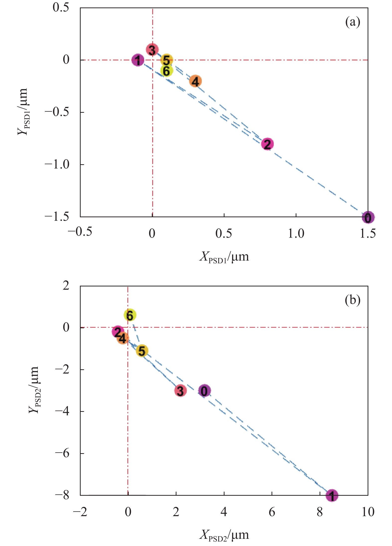
图6展示了单次光束的指向调控过程,图6(a)、图6(b)为PSD1、PSD2在6次迭代过程中的光斑变化,已标识迭代次序,光斑逐渐向中心靠近。图7展示了该指向调控过程的偏差变化,其中综合偏差$ {e}_{syn}=\left|{e}_{x1}\right|+\left|{e}_{z1}\right|+\left|{e}_{x2}\right|+\left|{e}_{z2}\right| $,由于位置偏差与角度偏差的调控相互制衡,偏差伴随小幅振荡现象,综合偏差的变化说明调控后的光束指向偏差下降趋势明显。

图 6 (a) PSD1和(b) PSD2光斑位置变化
Figure 6. Spot position changes of (a) PSD1 and (b) PSD2

图 7 迭代求解过程的偏差变化
Figure 7. Deviation change in iterative solution process
仿真环境设置同1.4节,基于此,收集1e3次实验数据。调控后,PSD1光斑质心偏差区间缩小为±[0.45 μm, 0.32 μm],PSD2光斑质心偏差区间缩小为±[1.49 μm, 1.06 μm],依据公式(9)可得角度偏差范围为±[2.98 μrad, 2.12 μrad],平均完成一轮指向调控的所需迭代步数为9.09。实验表明,迭代收敛策略可有效求解双快速反射镜偏转角,显著减少光束指向偏差,但所需迭代步数较高。
迭代收敛求解方法需多次迭代以得到较好的快速反射镜偏转角,借助迭代收敛求解积累的光斑位置偏差与偏转角数据,构建二者的直接映射能有效减少迭代次数及求解时间。神经网络是具有极强非线性逼近能力的拟合工具,可用于建立上述映射关系。
-
面向双快速反射镜偏转角求解问题,输入及输出向量维度较低,训练数据相对较少,适合以浅层神经网络(Shallow Neural Networks, SNN)建立该映射。以3.1节所述方法所积累的实验结果为数据集,输入为探测器偏差$ \left[{e}_{x1},{e}_{z1},{e}_{x2},{e}_{z2}\right] $,输出为快速反射镜偏转角$ \left[{{\theta }_{1}}_{v},{{\theta }_{1}}_{u},{{\theta }_{2}}_{v},{{\theta }_{2}}_{u}\right] $,唯一的隐含层拥有12个神经元,采用全连接形式,使用均方误差(Mean Square Error, MSE)为损失函数,网络结构如图8所示。原始数据集按8∶1∶1比例随机切分为训练集、验证集与测试集,辅以早停机制避免过拟合。训练结果显示,训练集、验证集与测试集的均方误差均小于4.33e-13,说明SNN络结构能较好地拟合探测器偏差到快速反射镜偏转角的映射关系。

图 8 SNN拓扑结构示意图
Figure 8. Schematic diagram of SNN topological structure
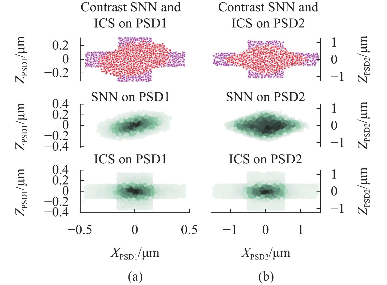
建立新的仿真环境,环境参数同1.4节,在相同条件下对比SNN与迭代收敛策略(Iterative Convergence Strategy, ICS)的差异,共执行1e4次测试,光斑偏差如图9所示,数据统计结果如表2所示。
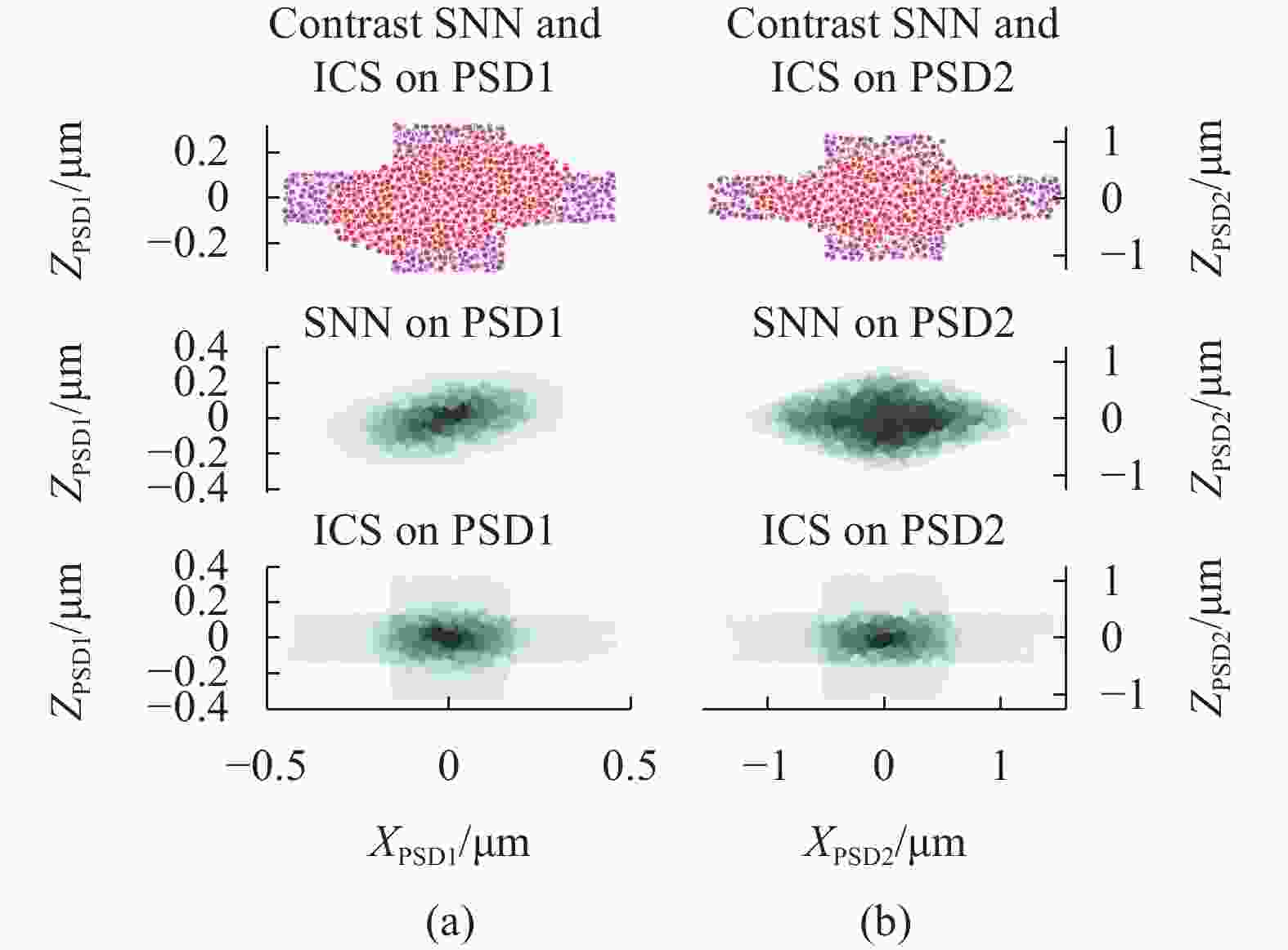
图 9 仿真环境下浅层神经网络与迭代收敛策略对比示意图
Figure 9. Comparison between SNN and ICS in the simulation environment
表 2 实验数据统计结果
Table 2. Statistical results of experimental data
Unregulate SNN ICS Position deviation range of PSD1/μm ±[51.83, 44.47] ±[0.35, 0.24] ±[0.45, 0.32] Angle deviation range of PSD2/μrad ±[236.60, 179.98] ±[2.20, 1.84] ±[3.00, 2.11] Max $ {e}_{syn} $/μm 251.75 1.66 2.06 Min $ {e}_{syn} $/μm 6.45 0.07 0.04 Mean $ {e}_{syn} $/μm 90.70 0.76 0.72 Average iteration - 1 9.09 实验表明,完成一轮光束指向调控的快速反射镜偏转角求解,浅层神经网络仅需一次求解,相比于迭代收敛策略平均需执行9.09次迭代,免去了多次迭代,极大提升了解算速度。浅层神经网络调控后,PSD1、PSD2光斑质心偏差范围指标均优于迭代收敛策略,综合偏差指标与迭代收敛策略相近;相较于未调控前光束状态,在X和Z方向的位置偏差分别减小99.32%和99.46%,角度偏差分别减小99.07%和98.98%,平均综合偏差减小99.16%,有效抑制了原光束指向失调。
面对光束指向调控的双快速反射镜偏转角求解问题,前期可执行迭代收敛策略求解并积累数据集,后期基于数据集训练浅层神经网络直接求解偏转角。浅层神经网络神经元参数较少,训练完毕后,可移植到FPGA实现硬件加速,提高系统响应性能。
-
为解决双快速反射镜的光束指向调控系统的偏转角求解问题,文中建立了双快速反射镜调控系统理论模型,讨论了快速反射镜偏转角与光斑位移的近似线性关系,提出了基于浅层神经网络的偏转角快速解算方法,在仿真环境下展开调控,相较于未调控前光束状态,在X和Z方向的位置偏差减小99.32%和99.46%,角度偏差减小99.07%和98.98%,平均综合偏差减小99.16%,光束指向偏差得到有效校正。在工程应用时,可根据实际光路参数构建仿真模型并积累仿真数据集,后续在实际光路中进行迭代收敛调控并形成真实数据集,基于二者进行集成学习、迁移学习及模型融合,降低浅层神经网络对训练数据量的要求。
A fast calculation method for deflection angles of dual fast steering mirrors for beam pointing control
-
摘要: 基于双快速反射镜的光束指向调控系统可补偿光束位置偏差及角度偏差,双反射镜引入的耦合效应致使难以快速求解合适的镜面绕轴偏转角。为解决该问题,文中构建了双快速反射镜光束指向调控模型,分析了偏转角与光斑位移在小角度下的近似线性关系,提出了偏转角的快速解算方法,可在单次求解后获得适用的镜面偏转角。该方法采用迭代收敛算法解算抑制随机光束指向失调的偏转角并形成数据集,基于该数据集训练浅层神经网络,可根据当前光斑位置偏差直接解算快速反射镜偏转角。仿真实验结果表明,依据该方法解算的偏转角进行调控,相较于未调控前光束状态,在X和Z方向的位置偏差分别减小99.32%、99.46%,角度偏差分别减小99.07%、98.98%,平均综合偏差减小99.16%,极大地抑制了光束指向失调。Abstract:
Objective Internal temperature drift, mechanical structure deformation, thermal effects of optical components, and other factors lead to misalignment of the emitted laser beam, causing drift of the spot on the target surface (Fig.1) and affecting laser applications. In order to suppress this phenomenon, it is necessary to establish a beam pointing control system. Currently, there are primarily two approaches of reflective approach using fast steering mirrors and transmission approach using rotating prisms. Control system with single fast steering mirror can correct the angle deviation of beam and the deflection angle is easy to calculate. However, it cannot address the coupling misalignment between the position and angle of the beam. Control system with dual fast steering mirror can simultaneously correct the position and angle deviation of the beam. However, it introduces coupling issues and makes it difficult to find suitable deflection angles. Currently, there have been numerous theoretical analyses on the reverse angle problem of prism rotation in the transmission approach, while the coupling theory of the dual fast steering mirrors remains unclear, and the linear fitting of mirror deflection angle and spot position offset lacks theoretical support. Therefore, it is necessary to explore in depth the inherent relationship between beam pointing and the deflection angles of dual fast steering mirrors and find a rational method to calculate the deflection angles. Methods The dual fast steering mirror beam pointing control system consists of two branched optical paths (Fig.2). Using ray tracing, a theoretical model of this system has been established (Tab.1). This model reflects the mathematical relationship between the beams and the deflection angles of the dual fast steering mirrors. Based on this model, a simulation environment can be created. By analyzing this theoretical model, it is observed that the complex coupling relationship between the deflection angles of the fast steering mirrors and the spot position deviation can be approximated as a linear relationship under small deflection angles. A fast calculation method for the deflection angles of the dual fast steering mirrors is proposed. Firstly, a data set of spot position deviations and deflection angles is collected using an iterative convergence strategy (Fig.5). Then, a shallow neural network is trained based on the historical data accumulated from iterative convergence strategy (Fig.8). Finally, the trained neural network is used to quickly determine the output deflection angles of the dual fast steering mirrors based on the input detector's spot position deviation. The data collection and neural network training processes of the iterative convergence strategy can be performed offline, without increasing the time required for beam pointing control. Results and Discussions The experimental results in the simulation environment demonstrate that the proposed iterative convergence strategy effectively solves the deflection angles for beam pointing control (Fig.6-7), with an average iteration step of 9.09. The fast calculation method based on shallow neural networks establishes a direct mapping between spot position deviation and deflection angles, and the result can be obtained after a single computation. The experimental results in the simulation environment show that compared to the beam state before control, the position deviation in the X and Z directions is reduced by 99.32% and 99.46% respectively, the angle deviation is reduced by 99.07% and 98.98% with the average comprehensive deviation being reduced by 99.16% (Tab.2). This method effectively suppresses the original beam misalignment. The shallow neural network only requires one-step solving process, eliminating the need for multiple iterations and greatly improving the calculation speed. Conclusions After the derivation and analysis of the theoretical model of the dual fast steering mirror beam pointing control system, the coupling phenomenon is explained, and it is demonstrated that there exists an approximate linear relationship between the deflection angle of the fast steering mirrors and the spot displacement under small angle conditions. The simulation experimental results show that with the proposed fast calculation method the deflection angles of dual fast steering mirrors for beam pointing control can be solved quickly and effectively. In engineering applications, a simulation model can be constructed based on the actual optical path parameters and form a simulation dataset. Subsequently, iterative convergence control can be performed in the actual optical path to form a real dataset. Integrated learning, transfer learning, and model fusion can be performed based on both datasets to reduce the requirement for a large training dataset for shallow neural networks. -
图 1 (a) 光束位置失调、(b) 光束角度失调及(c) 光束位置及角度耦合失调示意图
Figure 1. Schematic diagrams of (a) displacement of position, (b) displacement of angle and (c) displacement of position and angle
图 2 基于双快速反射镜的光束指向调控系统示意图
Figure 2. Schematic diagram of beam direction control system based on dual fast steering mirrors
图 3 (a) 角度和(b) 位置解耦光路
Figure 3. Example of (a) angle and (b) position decoupled optical path
图 4 (a) PSD1和(b) PSD2光斑位置偏差分布示意图
Figure 4. Statistical diagram of (a) PSD1 and (b) PSD2 spot position deviation
图 9 仿真环境下浅层神经网络与迭代收敛策略对比示意图
Figure 9. Comparison between SNN and ICS in the simulation environment
表 1 光路组件初始状态
Table 1. Initial status of the optical component
FSM1 FSM2 BS1 BS2 M1 ${x}_{ { {\boldsymbol{X} } }_{{\boldsymbol{p}}} }$/mm 0 200 200 200 100 ${y}_{ {{\boldsymbol{X}}}_{{\boldsymbol{p}}} }$/mm −100 −100 0 200 200 ${z}_{ {{\boldsymbol{X}}}_{{\boldsymbol{p}}} }$/mm 0 0 0 0 0 ${A}_{ {{\boldsymbol{n}}}_{{\boldsymbol{s}}} }$ $ \sqrt{2}/2 $ $ -\sqrt{2}/2 $ $ \sqrt{2}/2 $ $ -\sqrt{2}/2 $ $ \sqrt{2}/2 $ ${B}_{ {{\boldsymbol{n}}}_{{\boldsymbol{s}}} }$ $ \sqrt{2}/2 $ $ \sqrt{2}/2 $ $ -\sqrt{2}/2 $ $ -\sqrt{2}/2 $ $ \sqrt{2}/2 $ ${C}_{ {{\boldsymbol{n}}}_{{\boldsymbol{s}}} }$ 0 0 0 0 0  下载: 导出CSV
表 2 实验数据统计结果
Table 2. Statistical results of experimental data
Unregulate SNN ICS Position deviation range of PSD1/μm ±[51.83, 44.47] ±[0.35, 0.24] ±[0.45, 0.32] Angle deviation range of PSD2/μrad ±[236.60, 179.98] ±[2.20, 1.84] ±[3.00, 2.11] Max $ {e}_{syn} $/μm 251.75 1.66 2.06 Min $ {e}_{syn} $/μm 6.45 0.07 0.04 Mean $ {e}_{syn} $/μm 90.70 0.76 0.72 Average iteration - 1 9.09
下载: 导出CSV
-
[1] 邓汝杰, 张艺斌, 刘河山, 等 . 太极计划中的星间激光测距地面电子学验证 [J]. 中国光学,2023 ,16 (4 ):765 -776 . doi: 10.37188/CO.2022-0041 Deng Rujie, Zhang Yibing, Liu Heishan, et al. Ground electronics verification of inter-satellites laser rangingin the Taiji program [J]. Chinese Optics, 2023, 16(4): 765-776. (in Chinese) doi: 10.37188/CO.2022-0041[2] 张晓斌, 韩伟娜 . 角度复用的光学加密超表面的超快激光嵌套加工方法研究 [J]. 中国光学,2023 ,16 (4 ):889 -903 . doi: 10.37188/CO.2022-0228 Zhang Xiaobin, Han Weina. Angle-multiplexed optically encrypted metasurfaces fabricated by ultrafast laser induced spatially selective-modified nanograting structures [J]. Chinese Optics, 2023, 16(4): 889-903. (in Chinese) doi: 10.37188/CO.2022-0228[3] Arancibia N O P, Chen N, Gibson S, et al. Adaptive control of a MEMS steering mirror for suppression of laser beam jitter [C]//American Control Conference. IEEE, 2006. [4] 朱伟鸿, 汪洋, 王栎皓等 . 卫星激光通信MEMS快速反射镜可靠性研究进展 [J]. 红外与激光工程,2023 ,52 (9 ):20230179 . doi: 10.3788/IRLA20230179 Zhu Weihong, Wang Yang, Wang Lihao, et al. Research progress of reliability of MEMS fast steering mirror forsatellite laser communication [J]. Infrared and Laser Engineering, 2023, 52(9): 20230179. (in Chinese) doi: 10.3788/IRLA20230179[5] 姜玉鑫, 孙建锋, 侯培培, 等 . 基于Levenberg-Marquardt算法的旋转双棱镜指向偏差修正 [J]. 中国激光,2023 ,50 (6 ):0605001 . doi: 10.3788/CJL220634 Jiang Yuxin, Sun Jianfeng, Hou Peipei, et al. Correction of pointing deviation of risley prisms based on Levenberg-Marquardt algorithm [J]. Chinese Journal of Lasers, 2023, 50(6): 0605001. (in Chinese) doi: 10.3788/CJL220634[6] 杨峰, 石振东, 姜勇, 等 . 阵列光束棱镜扫描光束指向及点云精度分析 [J]. 红外与激光工程,2023 ,52 (5 ):20220689 . doi: 10.3788/IRLA20220689 Yang Feng, Shi Zhendong, Jiang Yong, et al. Analysis of point cloud accuracy and beam pointing of array beamthrough prism scanning [J]. Infrared and Laser Engineering, 2023, 52(5): 20220689. (in Chinese) doi: 10.3788/IRLA20220689[7] 李富豪, 赵继广, 杜小平等. 基于空间光通信的光束偏转技术研究现状及趋势分析[J]. 红外与激光工程, 2023, 52(10): 20230004. doi: 10.3788/IRLA20230004. Li Fuhao, Zhao Jiguang, Du Xiaoping. Research status and trend analysis of beam deflection technology based on space laser communication[J]. Infrared and Laser Engineering , 2023, 52(10): 20230004. (in Chinese) [8] 张玮钒, 颜昌翔, 高志良, 等 . 二自由度快速控制反射镜系统固有频率优化设计 [J]. 红外与激光工程,2021 ,50 (6 ):243 -254 . doi: 10.3788/IRLA20200450 Zhang Weifan, Yan Changxiang, Gao Zhiliang, et al. Optimal design of natural frequency of two-degree-of-freedomfast steering mirror system [J]. Infrared and Laser Engineering, 2021, 50(6): 20200450. (in Chinese) doi: 10.3788/IRLA20200450[9] 凡木文, 黄林海, 李梅, 等 . 抑制光束抖动的压电倾斜镜高带宽控制 [J]. 物理学报,2016 ,65 (2 ):154 -161 . doi: 10.7498/aps.65.024209 Fan Muwen, Huang Linhai, Li Mei, et al. High-bandwidth control of piezoelectric steering mirrorfor suppression of laser beam jitter [J]. Acta Physica Sinica, 2016, 65(2): 024209. (in Chinese) doi: 10.7498/aps.65.024209[10] 周睿, 李新阳, 沈锋, 等 . 基于两级高速倾斜镜闭环控制的光束稳定技术研究 [J]. 光学学报,2016 ,36 (12 ):139 -149 . doi: 10.3788/AOS201636.1214002 Zhou Rui, Li Xinyang, Shen Feng, et al. Laser beam stabilizing system based on close loop control of two fast steering mirrors in series [J]. Acta Optica Sinica, 2016, 36(12): 1214002. (in Chinese) doi: 10.3788/AOS201636.1214002[11] 王瑞, 苏秀琴, 乔永明, 等 . 基于双前馈+双神经网络自适应快速反射镜的解耦控制 [J]. 红外与激光工程,2021 ,50 (11 ):221 -227 . doi: 10.3788/IRLA20210194 Wang Rui, Su Xiuqin, Qiao Yongming, et al. Decoupling control of fast steering mirror based on dual feedforward+dual neural network adaptive [J]. Infrared and Laser Engineering, 2021, 50(11): 20210194. (in Chinese) doi: 10.3788/IRLA20210194[12] 任文佳, 刘瑾, 杨海马 . 模糊PID控制的光束指向稳定系统 [J]. 传感器与微系统,2022 ,41 (7 ):85 -88 . doi: 10.13873/J.1000-9787(2022)07-0085-04 Ren Wenjia, Liu Jing, Yang Haima. Fuzzy PID-controlled beam pointing stabilization system [J]. Transducer and Microsystem Technologies, 2022, 41(7): 85-88. (in Chinese) doi: 10.13873/J.1000-9787(2022)07-0085-04[13] 李鑫鹏, 于德洋, 潘其坤, 等 . 极紫外光刻光源系统光束指向稳定性研究 [J]. 激光与光电子学进展,2021 ,58 (17 ):272 -277 . doi: 10.3788/LOP202158.1714004 Li Xinpeng, Yu Deyang, Pan Qikun, et al. Beam pointing stability of extreme ultraviolet lithography light source system [J]. Laser & Optoelectronics Progress, 2021, 58(17): 1714004. (in Chinese) doi: 10.3788/LOP202158.1714004[14] 鲍建飞, 黄立华, 曾爱军等 . 光刻机照明系统中光束稳定技术研究 [J]. 中国激光,2012 ,39 (9 ):151 -157 . doi: 10.3788/CJL201239.0908004 Bao Jianfei, Huang Lihua, Zeng Aijun, et al. Study on beam stabilization technique in lithography illumination system [J]. Chinese Journal of Lasers, 2012, 39(9): 151-157. (in Chinese) doi: 10.3788/CJL201239.0908004[15] 马程鹏, 汤孟博, 孙琦, 等 . 分离式调控的高精度光束指向稳定系统 [J]. 光学精密工程,2023 ,31 (11 ):1607 -1618 . doi: 10.37188/OPE.20233111.1607 Ma Pengcheng, Tang Mengbo, Sun qi, et al. High-accuracy laser spatial alignment and stabilization system with error separation technology [J]. Optics and Precision Engineering, 2023, 31(11): 1607-1618. (in Chinese) doi: 10.37188/OPE.20233111.1607[16] 任行飞, 范晋伟, 潘日, 等 . 基于快速反射镜的光束指向性偏差矫正系统 [J]. 中国激光,2023 ,50 (14 ):1405003 . doi: 10.3788/CJL221459 Ren Xingfei, Fan Jinwei, Pan Ri, et al. Beam-pointing deviation correction system base on fast steering mirrors [J]. Chinese Journal of Lasers, 2023, 50(14): 1405003. (in Chinese) doi: 10.3788/CJL221459[17] 张鲁薇, 王卫兵, 王锐, 等 . 基于正解过程的Risley棱镜光束指向控制精度分析 [J]. 中国光学,2017 ,10 (4 ):507 -513 . doi: 10.3788/CO.20171004.0507 Zhang Luwei, Wang Weibing, Wang Rui, et al. Analysis of beam steering control precision for Risley prismsbased on forward solution [J]. Chinese Optics, 2017, 10(4): 507-513. (in Chinese) doi: 10.3788/CO.20171004.0507[18] 周远, 鲁亚飞, 黑沫, 等 . 旋转双棱镜光束指向的反向解析解 [J]. 光学精密工程,2013 ,21 (7 ):1693 -1700 . doi: 10.3788/OPE.20132107.1693 Zhou Yuan, Lu Yafei, Hei Mo, et al. Analytical inverse solutions for rotational double prism beam steering [J]. Optics and Precision Engineering, 2013, 21(7): 1693-1700. (in Chinese) doi: 10.3788/OPE.20132107.1693[19] Chen C G, Heilmann R K, Joo C, et al. Beam alignment for scanning beam interference lithography[J]. Journal of Vacuum Science & Technology, B. Microelectronics and Nanometer Structures : Processing, Measurement and Phenomena , 2002, 20(6): 3071-3074. -

 点击查看大图
计量
- 文章访问数: 52
- HTML全文浏览量: 15
- PDF下载量: 19
- 被引次数: 0

