


-
具有大长径比的深孔,如枪管、气缸和流道孔,在工业中应用广泛。深孔加工系统由于长径比大、刚度差,加工过程极易发生径向颤振,对深孔的圆度造成不利影响[1]。而圆度误差直接影响着产品的整体性能,例如降低发动机气缸的能量转换效率和冶金辊子的冷却性能[2]。
圆度误差的测量可分为接触和非接触两种方式。接触测量方式通过记录探头与被测表面接触后产生的电信号变化来反馈采样点的空间位置,方便高精度地获取被测参数,如三坐标测量机和圆度仪,但价格较为昂贵且在测量过程中可能会损伤表面。随着光电[3]、电磁、图像等技术的出现,非接触测量方法具有有效保护被测表面质量等优点,在形状误差测量领域不断得到应用,如基于电容法[4]、超声波法[5]、光纤强度法[6]和激光三角法[7]等单点扫描方式,但存在检测精度较低或测量范围有限的问题。Inari等[8]提出了一种基于圆结构光的测量系统,该系统通过圆锥反射镜反射激光束产生圆结构光,利用激光三角测量和近景摄影测量算法计算三维坐标。这种测量系统由于其灵活性强、精度高、结构简单等优点,得到了研究者们的广泛研究。
基于圆结构光测量的原理,研究人员对结构和原理进行了改进。Zhuang B H等[9]对检测器性能进行了理论分析,提高了系统分辨率。通过测量一个标准的环规来标定系统,这需要精确地对准探测器的轴,操作较为困难。Zhang G等[10]开发了一种将激光与圆锥反射镜分离并从相反方向拉伸到管道中的系统,由于激光仅被玻璃管折射一次,有利于减小系统误差。朱烨等[11-12]提出了一个具有四个自由度的激光平面数学模型和基于双目视觉的灵活激光平面标定技术,易于操作。
目前圆结构光系统在测量圆度时存在一定的系统误差:激光器、相机和待测深孔难以平行或同轴,无法准确测量圆截面。文中分析了系统误差的产生机理,基于圆结构光系统提出了一种准确测量深孔圆度的方法。该方法可对系统误差进行补偿,无需严格保持激光器、相机和待测深孔平行或同轴,并通过测量实验验证了其可行性。
-
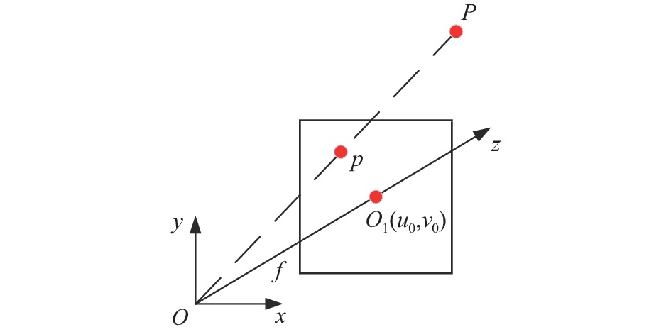
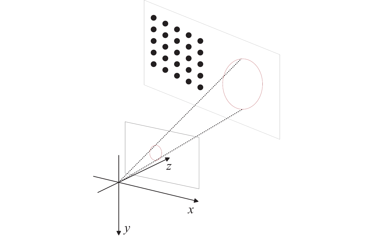
如图1所示,圆结构光测量系统由激光器、CMOS相机、相机镜头和一维导轨组成。激光器发出圆锥形结构光与待测深孔的内表面相交形成光环,CMOS相机对内表面上的光环进行拍摄,再根据圆结构光的基本原理得到光环上每个点的三维坐标。

图 1 圆结构光系统点坐标测量示意图
Figure 1. Schematic diagram of point coordinate measurement of circular structured light system
将相机坐标系Oxyz设为世界坐标系,z轴方向为相机光轴方向,图像平面即z=f的平面,O1(u0,v0)为光轴与图像平面的交点。采用如图2所示的小孔成像模型,则物点P(x,y,z)与像点p(u,v)的关系可表示为:

图 2 小孔成像模型
Figure 2. Small hole imaging model
$$ s\left[ \begin{gathered} u \\ v \\ 1 \\ \end{gathered} \right] = \left[ {\begin{array}{*{20}{c}} {{f_x}}&0&{{u_0}}&0 \\ 0&{{f_y}}&{{v_0}}&0 \\ 0&0&1&0 \end{array}} \right]\left[ {\begin{array}{*{20}{c}} x \\ y \\ z \\ 1 \end{array}} \right] $$ (1) 式中:s为比例因子,即物点在相机坐标系下的z坐标;fx=f/dx为u轴焦距;fy=f/dy为v轴焦距。${\boldsymbol{K}} = \left[ {\begin{array}{*{20}{c}} {{f_x}}&0&{{u_0}}&0 \\ 0&{{f_y}}&{{v_0}}&0 \\ 0&0&1&0 \end{array}} \right]$称为相机内参矩阵。
设(u,v)和(ud,vd)分别为理想像点和实际像点坐标,使用二阶径向畸变模型来描述:
$$ \left\{ \begin{gathered} {r^2} = ({x^2} + {y^2})/{z^2} \\ {u_{d}} = u + (u - {u_0})({k_1}{r^2} + {k_2}{r^4}) \\ {v_{d}} = v + (v - {v_0})({k_1}{r^2} + {k_2}{r^4}) \\ \end{gathered} \right. $$ (2) 式中:k1和k2为镜头的径向畸变参数。
圆结构光模型可以由空间的一般曲面方程来表示:
$$ \begin{split} & {a_1}{x^2} + {a_2}{y^2} + {a_3}{z^2} + {a_4}xy + {a_5}yz + {a_6}zx + {a_7}x +\\&\qquad\qquad {a_8}y + {a_9}z + 1 = 0 \end{split}$$ (3) 式中:ai=(1, 2, ···, 9)是表征圆结构光空间位置和形状的参数。
公式(1)和公式(2)表示经过畸变修正的成像光线,与公式(3)交会计算即可得到内表面物点的三维坐标。
-
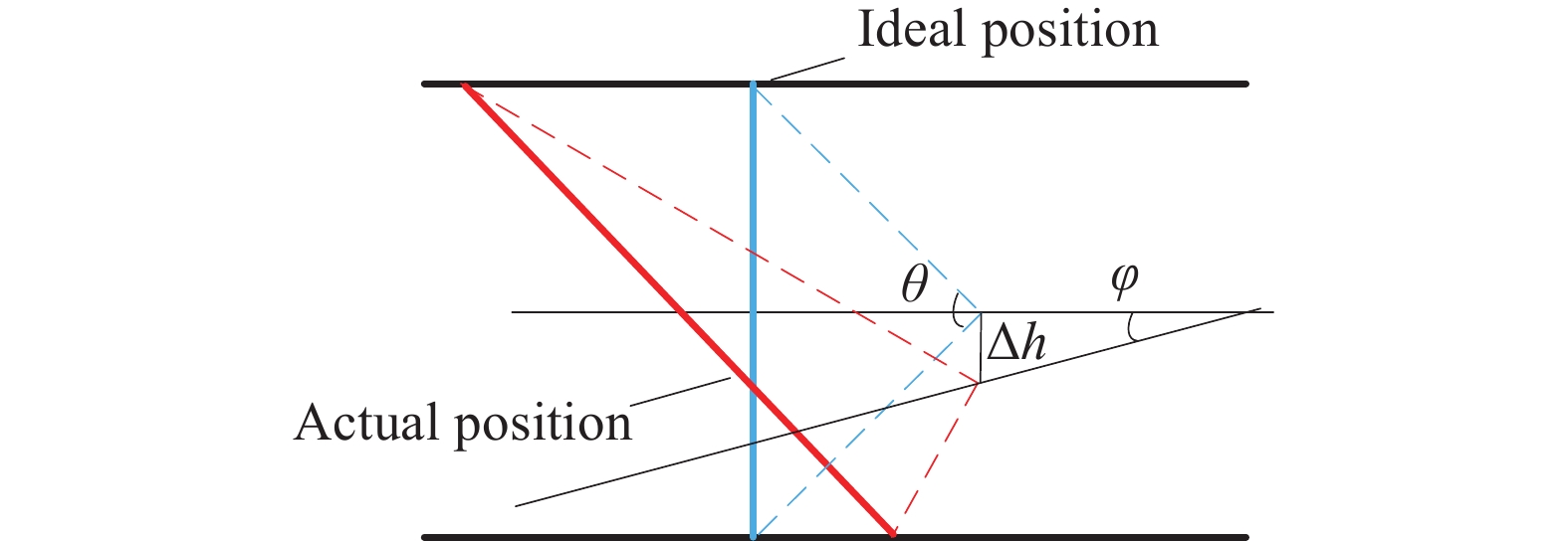
如图3所示,对于圆结构光系统,当激光器与待测内表面同轴时,测量的是理想截面。假设圆锥面的顶角为θ,距离中心的的误差量为Δh,误差角为φ。轴向左偏移量为$ \dfrac{{R + \Delta h}}{{\tan (\theta /2 - \varphi )}} - \dfrac{R}{{\tan (\theta /2)}} $,轴向右偏移量为$ \dfrac{R}{{\tan (\theta /2)}} - \dfrac{{R - \Delta h}}{{\tan (\theta /2 + \varphi )}} $。

图 3 圆结构光系统测量误差分析示意图
Figure 3. Schematic diagram of measurement error analysis of circular structured light systems
则轴向总偏移量为:
$$ {e} = \dfrac{{R + \Delta h}}{{\tan (\theta /2 - \varphi )}} - \dfrac{{R - \Delta h}}{{\tan (\theta /2 + \varphi )}} $$ (4) 通过以上分析,圆结构光系统测量时同时受到平行度和同轴度的影响,容易产生误差。
-
针对2.2节中的系统误差,提出一种圆度测量方法进行一定补偿。
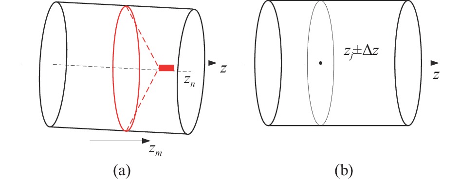
如图4(a)所示,利用电动直线滑台移动待测深孔零件完成全场测量。将电动直线滑台的移动方向表示为一个方向向量zm=[mx my mz]T,则被测深孔内表面上任一测量点的三维坐标[xj yj zj]T可由下式得到:

图 4 圆结构光系统圆度测量原理图。(a)刚体变换前;(b)刚体变换后
Figure 4. Schematic diagram of circular structured light system roundness measurement. (a) Before rigid body transformation; (b) After rigid body transformation
$$ {\left[ {{x_i}}\;\;{{y_i}}\;\;{{z_i}} \right]^{{\mathrm{T}}}} = {\left[ x\;\;y\;\;z \right]^{{\mathrm{T}}}} + n \cdot D \cdot {\left[ {{m_x}}\;\;{{m_y}}\;\;{{m_z}} \right]^{{\mathrm{T}}}} $$ (5) 式中:n表示被测深孔内表面被测界面的序号(从0开始);D表示两个被测截面之间电动直线滑台移动的步距。
通过上述原理可得出深孔内表面的三维点云坐标,拟合求出内表面轴线的方向向量zn,z轴的方向向量z=[0 0 1]T,则两向量的旋转矩阵Rz可由罗德里格斯(Rodrigues)公式求得。将点云刚体变换到轴线与z轴平行的位置,可得:
$$ {\left[ {{x_j}}\;\;{{y_j}}\;\;{{z_j}} \right]^{{\mathrm{T}}}} = {{{R}}_z}{\left[ {{x_i}}\;\;{{y_i}}\;\;{{z_i}} \right]^{{\mathrm{T}}}} $$ (6) 对位置为zj的截面进行圆度测量,则搜索z坐标为zj±Δz(Δz较小)的测量点作为圆度评定点,如图4(b)所示。
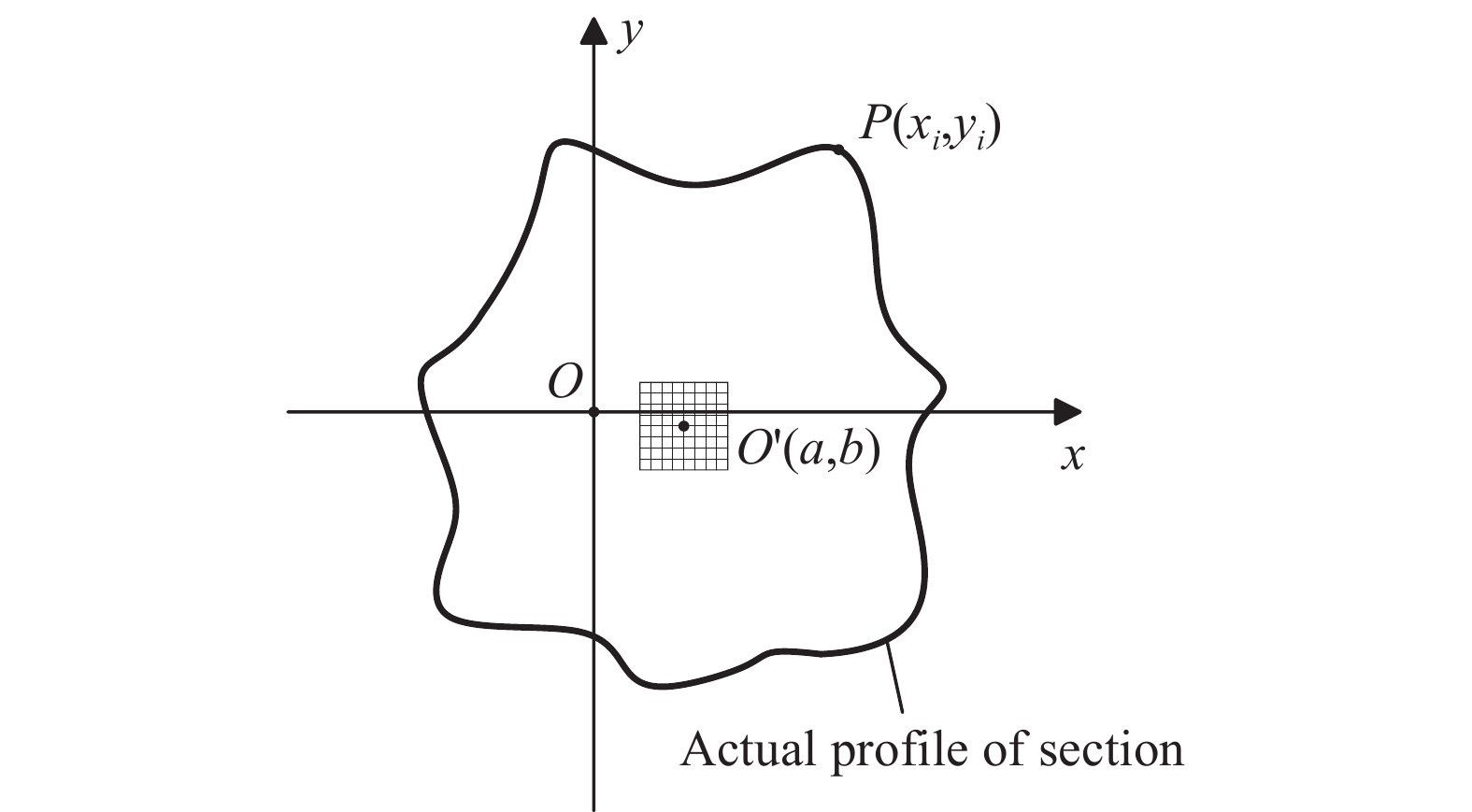
根据圆度评定点坐标数据信息P(xj,yj)(j=1, 2, ···, n),选用网格搜索算法评定其圆度[13]。如图5所示,以最小二乘圆心O'(a,b)为中心构建正方形网格点。依次以网格点为圆心,计算各个测点坐标与圆心坐标的半径。依据最小区域法确定相对应的圆心坐标点,从而得到圆度误差。

图 5 网格搜索算法示意图
Figure 5. Schematic diagram of grid search algorithm
评定步骤如下:
1)根据测点坐标P(xj,yj) (j=1, 2, ···, n)求出最小二乘圆心坐标O'(a,b);
2)以最小二乘圆心为中心构建正方形网格;
3)依次以网格点为圆心求最大半径Rmax和最小半径Rmin;
4)求得符合最小条件的圆度误差值f=min(Rmax–Rmin)。
-
文中采用文献[14]的方法进行系统标定。如图6所示,将一个平面靶标放置在激光器与工业相机之间,CMOS相机对平面靶标上形成的光环进行拍摄,移动靶标,拍摄4幅平面靶标处于不同位置的照片。通过张正友法进行相机标定,得到相机内部参数(u0、v0、fx和fy)以及镜头畸变参数(k1和k2)如表1所示,同时得到每个平板靶标的旋转矩阵R和平移向量t。

图 6 系统标定示意图
Figure 6. Schematic diagram of system calibration
表 1 相机内部参数和镜头畸变参数
Table 1. Internal camera parameters and lens distortion parameters
Parameter Value u0 2715.9593 v0 1841.3643 fx 15127.5219 fy 15127.9817 k1 −0.0796 k2 0.5261 平面靶标上光条的物点记为M=[x y 1]T,像点记为m=[u v]T,相应的齐次坐标为$\tilde M$=[x y 1]T和$\tilde m$=[u v 1]T,两者的关系为:
$$ s\tilde m = H\tilde M $$ (7) 式中:s为比例因子;H=K[r1 r2 t]=[h1 h2 h3]。
由公式(7)可得:
$$ {\left[ x\;\;y\;\;1 \right]^{{\mathrm{T}}}} = s{H^{ - 1}}{\left[ u\;\;v\;\;1 \right]^{{\mathrm{T}}}} $$ (8) 转化到相机坐标系下:
$$ {[ {{x_c}}\;\;{{y_c}}\;\;{{z_c}} ]^{{\mathrm{T}}}} = R{[ x\;\;y\;\;0 ]^{{\mathrm{T}}}} + t $$ (9) 将得到的圆结构光特征点进行最小二乘拟合,得到圆结构光参数ai=(1, 2, ···, 9)。
表 2 圆结构光参数
Table 2. Circular structured light parameters
Parameter Value a1 −0.00007745 a2 −0.00007774 a3 0.00000987 a4 0.00000001 a5 −0.00000038 a6 −0.00000044 a7 −0.00050127 a8 −0.00016611 a9 −0.00628916 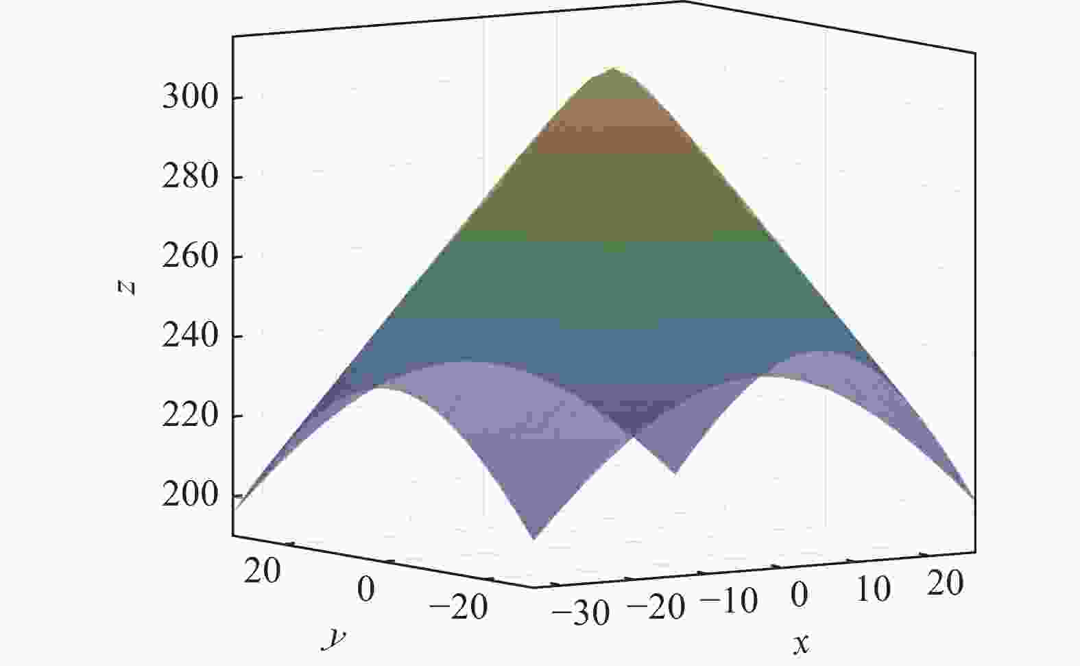
图 7 圆结构光拟合结果
Figure 7. Circular structure light fitting results
选定平面靶标的一个点为目标点,通过公式(6)得到目标点在相机坐标系下的坐标,目标点的移动轨迹反映了电动直线滑台的移动方向,标定结果为:
$$ {\left[ {{m_x}}\;\;{{m_y}}\;\;{{m_z}} \right]^{{\mathrm{T}}}} = {\left[ {0.022\;4}\;\;{ - 0.010\;0}\;\;{0.997\;0} \right]^{{\mathrm{T}}}} $$ (10) -
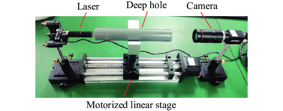
如图8所示,文中搭建的系统由650 nm激光器、海康的25 mm焦距镜头、海康的2 000万像素黑白CMOS工业相机和电动直线滑台组成,以内径23 mm的深孔零件作为测量对象。
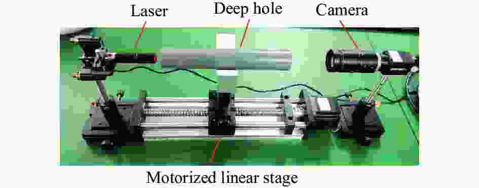
图 8 圆结构光系统圆度测量实验
Figure 8. Roundness measurement experiment of circular structured light system
根据硬件选型给出圆结构光系统的测量范围:测量对象为通孔;内径范围为20~50 mm,根据镜头范围而定;测量深度为90 mm,取决于激光器的长度和电动直线滑台的行程,在激光器后加伸长杆可提高测量深度。
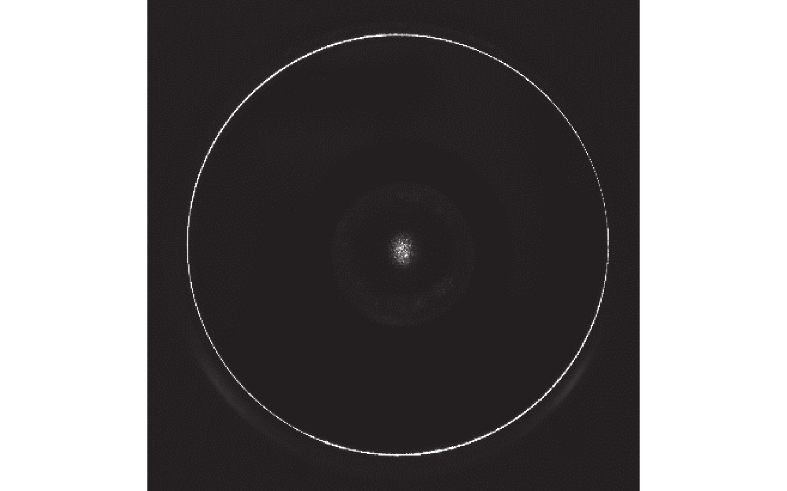
电动直线滑台以0.01 mm的步长对待测内表面进行扫描测量,到一定距离后停下。每一步拍摄一幅光环图像,拍摄的圆结构光图像如图9所示。
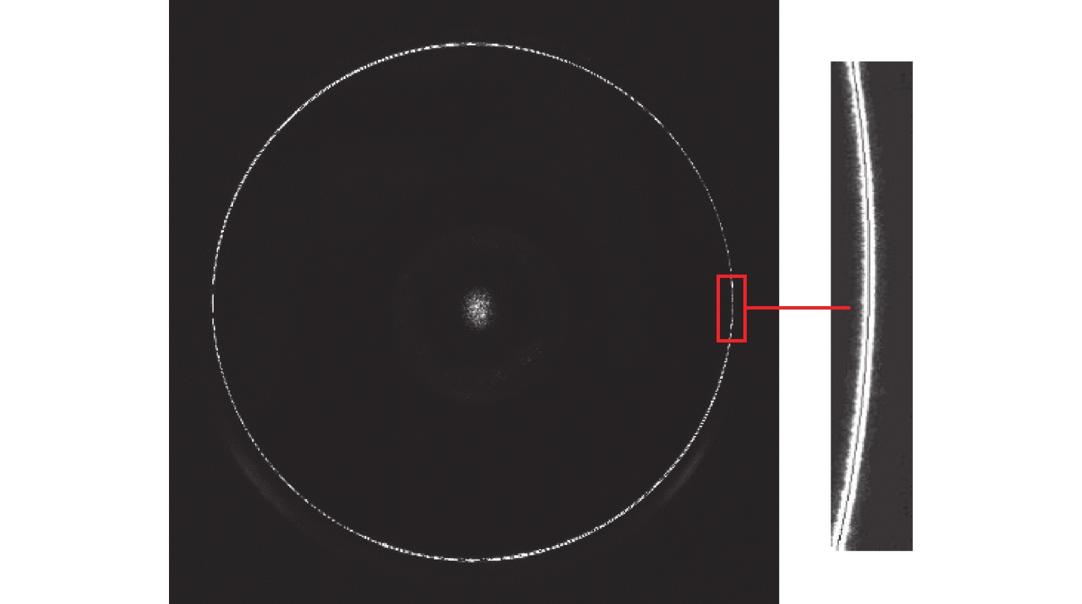
通过Steger算法[15]提取图像光环的亚像素中心点,具体步骤如下:
1)通过Hessian矩阵获得光环的法线方向;
2)在法线方向上对像素灰度应用泰勒多项式展开,得到灰度分布函数;
3)对该法线方向上的灰度分布函数的二阶泰勒多项式求取极值,得到中心点坐标。
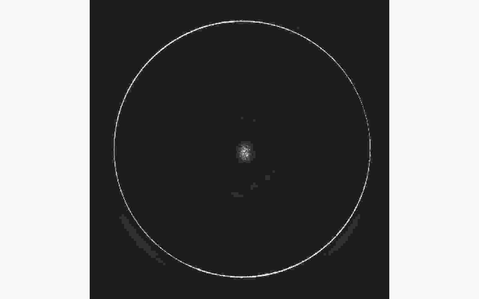
图 9 实验中拍摄的光环图像
Figure 9. Images of the halo taken during the experiment
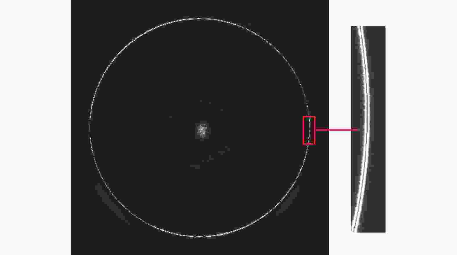
图 10 光环中心点提取结果
Figure 10. Results of halo center point extraction
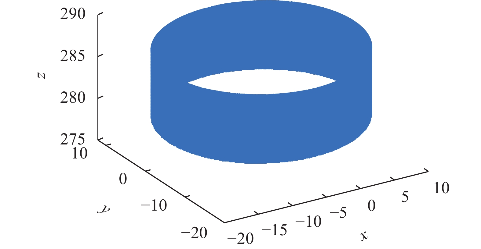
根据上文介绍的测量算法,最终得到的待测内表面高分辨率三维点云如图11所示。

图 11 待测内表面三维点云
Figure 11. 3D point cloud of the inner surface to be measured
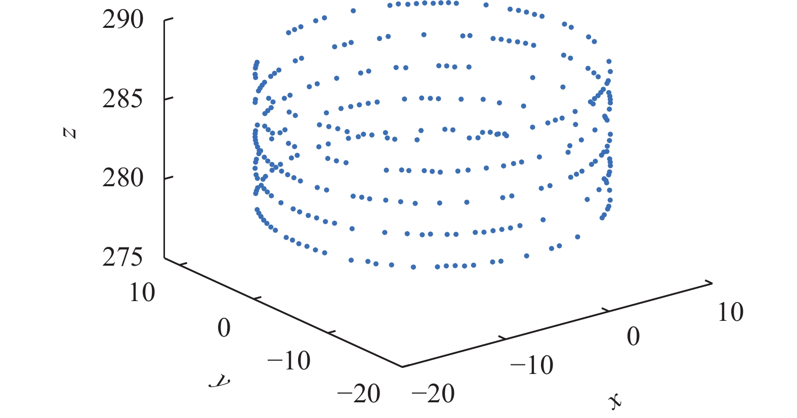
选取等间隔的5个截面,将补偿前的结果作为初始值,经过圆度测量方法补偿的结果作为测量值(图12),由FARO型三坐标测量机获得参考值,其单点测量精度为2 μm,均基于第2.2节的网格搜索算法进行评定,评定结果见表3。
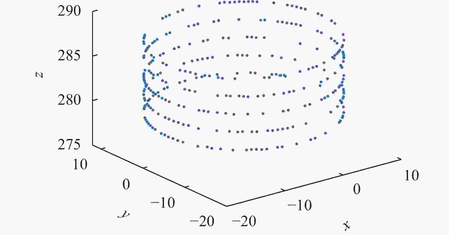
图 12 5个截面的圆度评定点
Figure 12. Roundness assessment points for 5 sections
表 3 5个截面的圆度评定结果
Table 3. Roundness evaluation results of 5 cross sections
Result Number 1 2 3 4 5 Reference/µm 23.4 21.5 21.2 19.1 21.4 Initial/µm 49.5 50.1 47.3 55.6 49.7 Measurement/µm 28.6 25.4 25.3 23.9 26.5 Error before compensation/µm 26.1 28.6 26.1 36.5 28.3 Error after compensation/µm 5.2 3.9 4.1 4.8 5.1 对补偿前的测量系统进行不确定度分析:
1)测量系统对同一截面重复测量5次,结果如表4所示,不确定分量u1=1.14$ \sqrt {\displaystyle\sum\limits_{i = 1}^n {{{({x_i} - \bar x)}^2}/n(n - 1)} } $=0.1885 µm。
表 4 补偿前单个截面的5次圆度评定结果
Table 4. Results of 5 roundness evaluations of a single section before compensation
Number Measurement/µm 1 48.3 2 50.7 3 50.4 4 47.4 5 51.2 2)三坐标测量机的单点测量精度为2 μm,不确定度分量$u_2=2 / \sqrt{3}= $=1.1547 µm。
3)测量系统的测量值与三坐标测量机的参考值进行对比,不确定度分量u3=29.12 µm。
最终得到圆度误差的不确定度为u = $ \sqrt {{u_1}^2 + {u_2}^2 + {u_3}^2} $=29.14 μm。
对补偿后的测量系统进行不确定度分析:
1)测量系统对同一截面重复测量5次,结果如表5所示,不确定分量u1=1.14$ \sqrt {\sum\limits_{i = 1}^n {{{({x_i} - \bar x)}^2}/n(n - 1)} } $=0.4032 µm。
表 5 补偿后单个截面的5次圆度评定结果
Table 5. Results of 5 roundness evaluations of a single section after compensation
Number Measurement/µm 1 26.4 2 27.4 3 27.1 4 25.4 5 26.9 2)三坐标测量机的单点测量精度为2 μm,不确定度分量$u_2=2 / \sqrt{3}= $=1.1547 µm。
3)测量系统的测量值与三坐标测量机的参考值进行对比,不确定度分量u3=4.62 µm。
最终得到圆度误差的不确定度为u=$ \sqrt {{u_1}^2 + {u_2}^2 + {u_3}^2} $=4.78 μm。
结果表明,经过圆度测量方法补偿后的系统测量不确定度比补偿前得到了较大的提升,说明该方法具有可行性。
-
文中研究搭建了圆结构光三维测量系统,对圆结构光系统测量圆度时的系统误差进行了分析,并提出了一种准确测量圆度的方法对系统误差进行补偿。通过测量实验验证了该方法测量圆度具有良好的补偿效果,其中测量不确定度为4.78 µm。
Deep hole roundness measurement method of circular structured light system
-
摘要: 圆结构光系统测量深孔(通孔)圆度时存在激光器、相机和深孔难以保持平行或同轴的问题,导致无法测量准确的圆截面,从而产生系统误差。搭建了基于圆结构光的测量系统,分析了系统误差的产生机理并提出了一种基于圆结构光系统测量圆度的方法,可对系统误差进行一定补偿:首先,获取待测深孔的内表面高分辨率三维点云,拟合点云轴线,通过刚体变换将三维点云变换到深孔轴线与相机光轴平行的位置;然后,选定一个测量截面,搜索该截面上的点和与该截面范围较近的点作为圆度评定点;最后,采用网格搜索算法完成圆度评定。测量实验的结果表明,该方法对于圆度误差的补偿效果良好,其中测量不确定度为4.78 µm。Abstract:
Objective The circular structured light based measurement system can generate circular structured light by reflecting a laser beam through a conical reflector, and utilizing laser triangulation and close-view photogrammetry algorithms to calculate three-dimensional coordinates. This kind of measurement system has been widely studied by researchers due to its advantages such as high flexibility, high accuracy and simple structure. The current circular structured light system has certain problems in measuring roundness. It is difficult for the laser, the camera and the deep hole to be measured to be parallel or coaxial, which leads to the inability to measure the accurate circular cross-section. A measurement system based on circular structured light is constructed, the mechanism of systematic error is analyzed and a method based on the circular structured light system to measure circularity is proposed, which provides some compensation for systematic errors. Methods The mechanism that generates systematic errors in the measurement of roundness by the circular structured light system is analyzed (Fig.3). A high-precision electric linear slide is used to move the deep hole parts to be measured to complete the full-field measurement, and a high-resolution point cloud is obtained and fit the axis. Through the Rodrigues formula, the inner surface point cloud rigid body will be transformed to the point cloud axis and z-axis parallel to the location of the point cloud axis, searching for the z coordinate near the point as a cross-section of the roundness of the assessment point (Fig.4). The roundness evaluation is completed by the grid search algorithm (Fig.5). Results and Discussions The compensation by the proposed method works well in roundness measurement experiments, in which the measurement uncertainty is 4.78 µm (Tab.3). For the circular structured light measurement system, a long rod can be assembled after the laser to increase the axial measurement range of the system. For the proposed circular structured light roundness measurement method, the resolution of the 3D point cloud can be improved by reducing the step length of the motorized linear slide to further improve the measurement accuracy. Conclusions A three-dimensional measurement system of circular structured light is built, the error generated when the circular structured light system measures roundness is analyzed, and a method based on the circular structured light system to accurately measure roundness is proposed. It is verified that the use of the method to measure roundness has a good compensating effect through the measurement experiments. -
图 1 圆结构光系统点坐标测量示意图
Figure 1. Schematic diagram of point coordinate measurement of circular structured light system
图 3 圆结构光系统测量误差分析示意图
Figure 3. Schematic diagram of measurement error analysis of circular structured light systems
图 4 圆结构光系统圆度测量原理图。(a)刚体变换前;(b)刚体变换后
Figure 4. Schematic diagram of circular structured light system roundness measurement. (a) Before rigid body transformation; (b) After rigid body transformation
图 8 圆结构光系统圆度测量实验
Figure 8. Roundness measurement experiment of circular structured light system
表 1 相机内部参数和镜头畸变参数
Table 1. Internal camera parameters and lens distortion parameters
Parameter Value u0 2715.9593 v0 1841.3643 fx 15127.5219 fy 15127.9817 k1 −0.0796 k2 0.5261  下载: 导出CSV
表 2 圆结构光参数
Table 2. Circular structured light parameters
Parameter Value a1 −0.00007745 a2 −0.00007774 a3 0.00000987 a4 0.00000001 a5 −0.00000038 a6 −0.00000044 a7 −0.00050127 a8 −0.00016611 a9 −0.00628916
下载: 导出CSV
表 3 5个截面的圆度评定结果
Table 3. Roundness evaluation results of 5 cross sections
Result Number 1 2 3 4 5 Reference/µm 23.4 21.5 21.2 19.1 21.4 Initial/µm 49.5 50.1 47.3 55.6 49.7 Measurement/µm 28.6 25.4 25.3 23.9 26.5 Error before compensation/µm 26.1 28.6 26.1 36.5 28.3 Error after compensation/µm 5.2 3.9 4.1 4.8 5.1
下载: 导出CSV
表 4 补偿前单个截面的5次圆度评定结果
Table 4. Results of 5 roundness evaluations of a single section before compensation
Number Measurement/µm 1 48.3 2 50.7 3 50.4 4 47.4 5 51.2
下载: 导出CSV
表 5 补偿后单个截面的5次圆度评定结果
Table 5. Results of 5 roundness evaluations of a single section after compensation
Number Measurement/µm 1 26.4 2 27.4 3 27.1 4 25.4 5 26.9
下载: 导出CSV
-
[1] 郑亮奎, 郑建明, 李旭波等. 错齿BTA深孔振动钻削刀具系统径向减振特性研究 [J]. 振动与冲击, 2019, 38(14): 96-104. Zheng Liangkui, Zheng Jianming, Li Xubo, et al. Radial damping characteristics of a drilling tool system in BTA deep-hole vibration drilling [J]. Journal of Vibration and Shock, 2019, 38(14): 96-104. (in Chinese) [2] 宋慈, 焦黎, 王西彬等. 面向轴孔类零件圆度误差评定的改进式最小区域圆法 [J]. 中国机械工程, 2022, 33(9): 1090-1097. Song Ci, Jiao Li, Wang Xibin, et al. Improved minimum zone circle method for roundness error evaluation of shaft and hole parts [J]. China Mechanical Engineering, 2022, 33(9): 1090-1097. (in Chinese) [3] 李超, 申力, 施斐斐. 同轴空心激光检测圆柱内孔圆度误差的方法研究(英文)[J]. 红外与激光工程, 2018, 47(S1): Li Chao, Shen Li, Shi Feifei. Research on the method of detecting the roundness error of cylindrical inner-hole by using coaxial hollow laser [J]. Infrared and Laser Engineering , 2018, 47(S1): S106001. [4] 李红民, 郭立杨, 宋冠锋等. 基于电容传感器管道焊缝位置检测方法的研究 [J]. 宇航计测技术, 2018, 38(1): 68-73. Li Hongmin, Guo Liyang, Song Guanfeng, et al. Research on the detection method of pipeline welding position based on capacitance sensor [J]. Journal of Astronautic Metrology and Measurement, 2018, 38(1): 68-73. (in Chinese) [5] 梁海波, 王怡. 基于深度学习的天然气钢制管道缺陷检测方法研究 [J]. 电子测量与仪器学报, 2022, 36(9): 148-158. Liang Haibo, Wangyi. Research on defect detection method of natural gas steel pipeline based on deep learning [J]. Journal of Electronic Measurement and Instrumentation, 2022, 36(9): 148-158. (in Chinese) [6] 徐伟. 基于光纤传感器的深孔内表面粗糙度测量方法研究[D]. 江苏大学, 2019. Xu Wei. Research on detection method of inner surface roughness for deep hole based on fiber optical sensor[D]. Zhenjiang: Jiangsu University, 2019. (in Chinese) [7] 张欣婷, 亢磊, 安志勇等. 改进型激光三角测头设计 [J]. 红外与激光工程, 2018, 47(10): 305-309. Zhang Xinting, Kang Lei, An Zhiyong, et al. Improved laser triangulation probe design [J]. Infrared and Laser Engineering, 2018, 47(10): 1018002. (in Chinese) [8] Inari T , Takashima K , Watanabe M, et al. Optical inspection system for the inner surface of a pipe using detection of circular images projected by a laser source[J]. Measurement , 1994, 13(2): 99-106. [9] Zhuang B H, Zhang W, Cui D Y. Noncontact laser sensor for pipe inner wall inspection [J]. Optical Engineering, 1998, 37(5): 1643-1647. doi: 10.1117/1.601677 [10] Zhang G, He J, Li X. 3D vision inspection for internal surface based on circle structured light[J]. Sensors & Actuators A Physical , 2005, 122(1): 68-75. [11] Zhu Y, Wang L, Gu Y, et al. Three-dimensional inner surface inspection system based on circle-structured light [J]. J Manuf Sci Eng, 2018, 140(12): 121007. doi: 10.1115/1.4041480 [12] Zhu Y, Wang L, Gu Y, et al. A laser triangulation-based 3D measurement system for inner surface of deep holes [C]//ASME 2018 13th International Manufacturing Science and Engineering Conference, 2018. [13] 雷贤卿, 畅为航, 薛玉君等. 圆度误差的网格搜索算法 [J]. 仪器仪表学报, 2008(11): 2324-2329. Lei Xianqing, Chang Weihang, Xue Yujun, et al. Evaluation of roundness error based on mesh search algorithm [J]. Chinese Journal of Scientific Instrument, 2008(11): 2324-2329. (in Chinese) [14] 孙军华, 张广军, 刘谦哲等. 结构光视觉传感器通用现场标定方法 [J]. 机械工程学报, 2009, 45(3): 174-177. doi: 10.3901/JME.2009.03.174 Sun Junhua, Zhang Guangjun, Liu Qianzhe, et al. Universal method for calibrating structured-light vision sensor on the spot [J]. Journal of Mechanical Engineering, 2009, 45(3): 174-177. (in Chinese) doi: 10.3901/JME.2009.03.174 [15] Yang Mingming, Wu Haibin, Chen Xinbing. Improved center strip extraction algorithm based on Steger algorithm [C]//3rd International Conference on Laser, Optics, and Optoelectronic Technology (LOPET 2023), SPIE, 2023, 12757: 366-370. -

 点击查看大图

计量
- 文章访问数: 20
- HTML全文浏览量: 1
- PDF下载量: 3
- 被引次数: 0

